If you work with metal, manufacture parts, or buy turned components – this is the only guide you need. This page covers everything from first principles to procurement decisions: how lathes work, every major operation, all tool types, the real cost of CNC vs manual, and how to avoid the errors that destroy tolerances and budgets.
In the next 10 minutes, you will know:
What Is Lathe Machining? (Foundation Definition)
Lathe machining is a subtractive manufacturing process in which a workpiece is rotated about its central axis while a stationary or CNC-controlled cutting tool removes material to produce precise cylindrical, conical, threaded, or profiled features.
The result is a part with rotational symmetry – shafts, sleeves, flanges, pins, bushings, and threaded fasteners are the canonical outputs, though modern multi-axis CNC lathes also produce asymmetric and highly complex turned parts.
The mental model: a sharp chisel vs. a spinning log
Picture a wooden log mounted horizontally and spinning at high speed. A craftsman presses a chisel against the surface and the rotating wood removes material in continuous ribbons. A metal lathe operates on the same principle – but with rigid machine castings, precision-ground slides, hydraulic workholding, and controlled feeds measured in thousandths of a millimeter, allowing tolerances in the micron range on hardened steels, titanium alloys, and exotic materials.
Real-world analogy
Think of pottery on a wheel: the clay spins and the potter’s hands (the “tool”) shape it. The lathe is the industrial-grade, metal version of that – not free-form but precisely programmed, mechanically constrained, and repeatable across thousands of parts.
Why it matters
- Turning is the most widely used machining process globally, covering more production volume than milling, grinding, or EDM combined.
- A huge proportion of all mechanical assemblies – engines, transmissions, pumps, turbines, medical implants – contain turned parts.
- CNC turning delivers tolerances as tight as ±0.005 mm and surface finishes Ra ≤ 0.8 μm in production conditions.
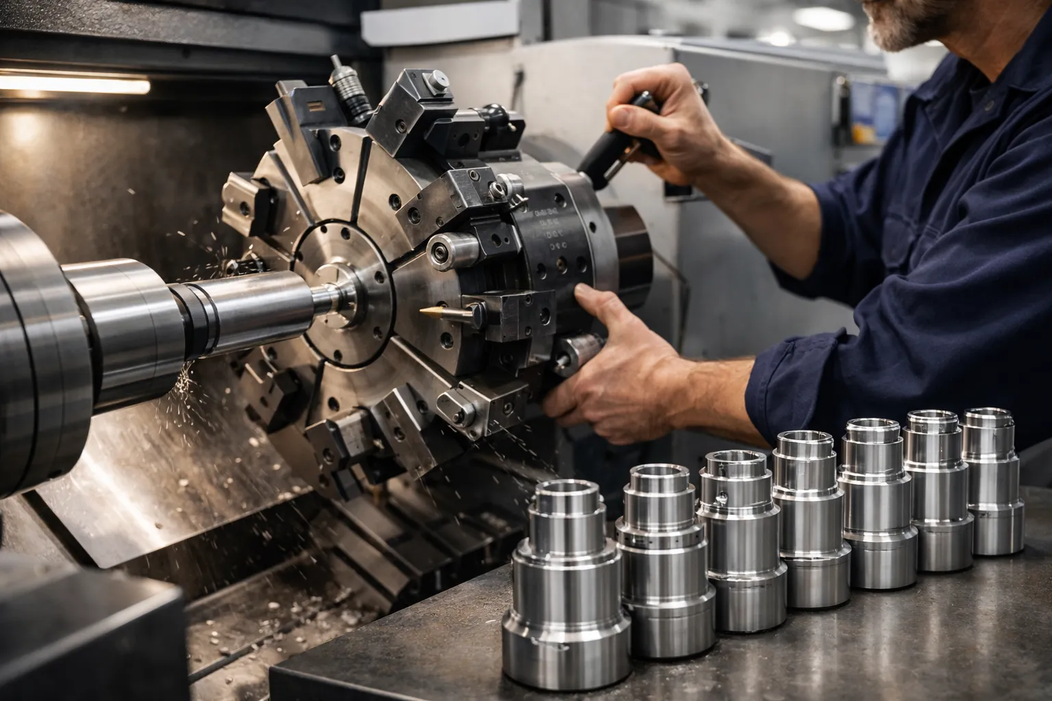
How a Lathe Machine Works (Step-by-Step)
Every lathe – from a 1950s manual engine lathe to a live-tooling CNC turning center – uses the same four-step kinematic process.
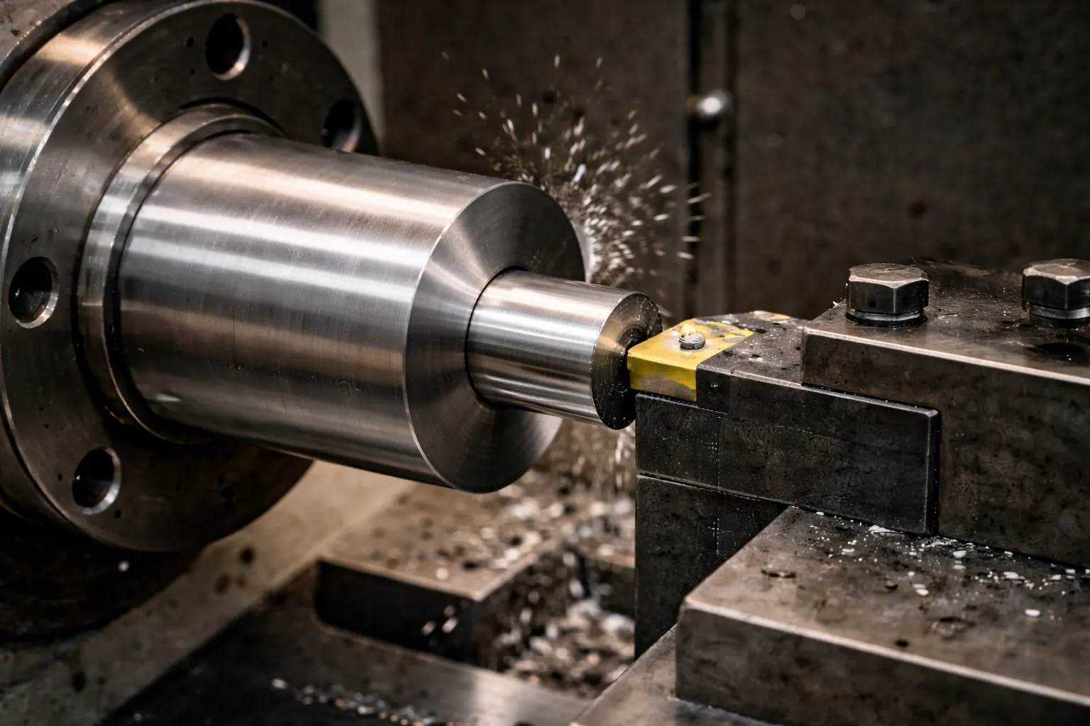
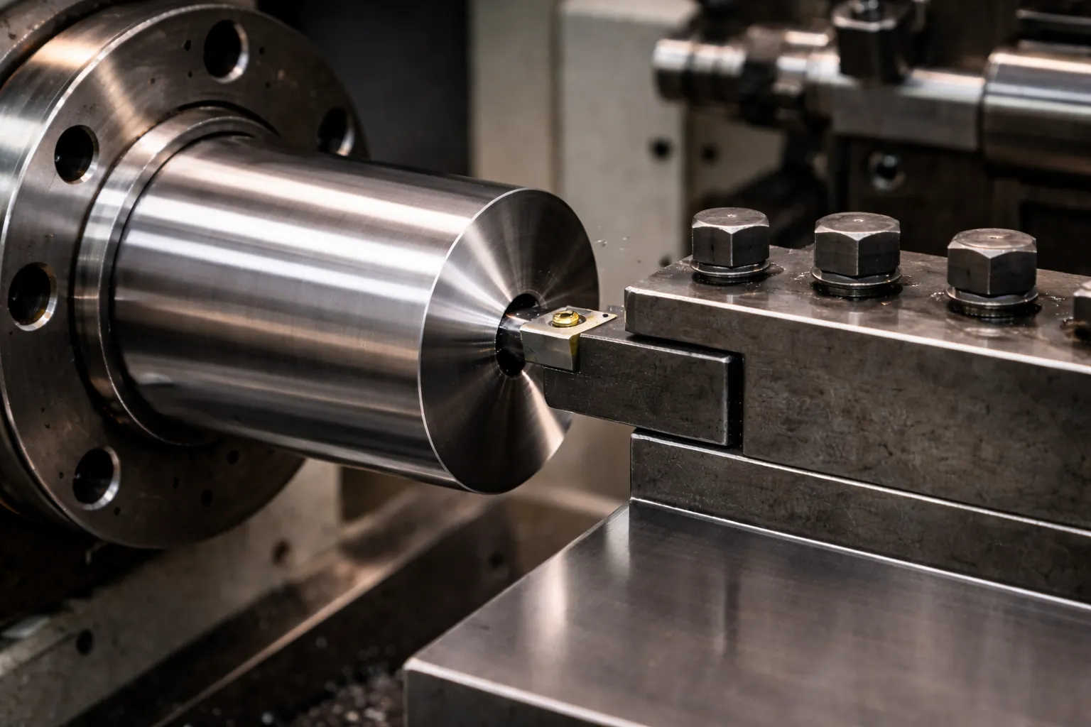
Step 1 – Rotation: the spindle drives the workpiece
A motor (belt-driven or direct-drive) spins the headstock spindle at a selected RPM. The workpiece, clamped in a chuck or between centers, rotates with the spindle. Spindle speed (RPM) is chosen based on workpiece diameter and tool material to achieve the correct cutting surface speed (SFM/m·min⁻¹) for the material being cut.
Step 2 – Tool engagement: feed and depth of cut
The cutting tool, rigidly clamped in the tool post, is moved toward the rotating workpiece by advancing the cross slide (X axis) for diameter control and the carriage (Z axis) for length travel. On manual lathes, the operator controls these axes via handwheels or power feed levers. On CNC lathes, servo-driven ball screws follow pre-programmed G-code paths with sub-micron resolution.
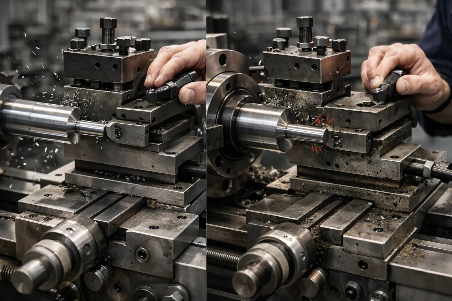
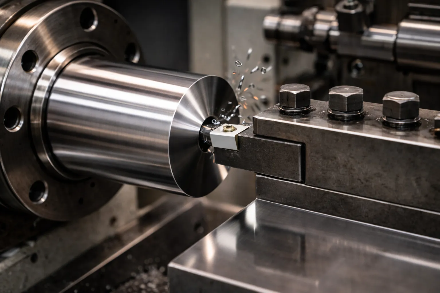
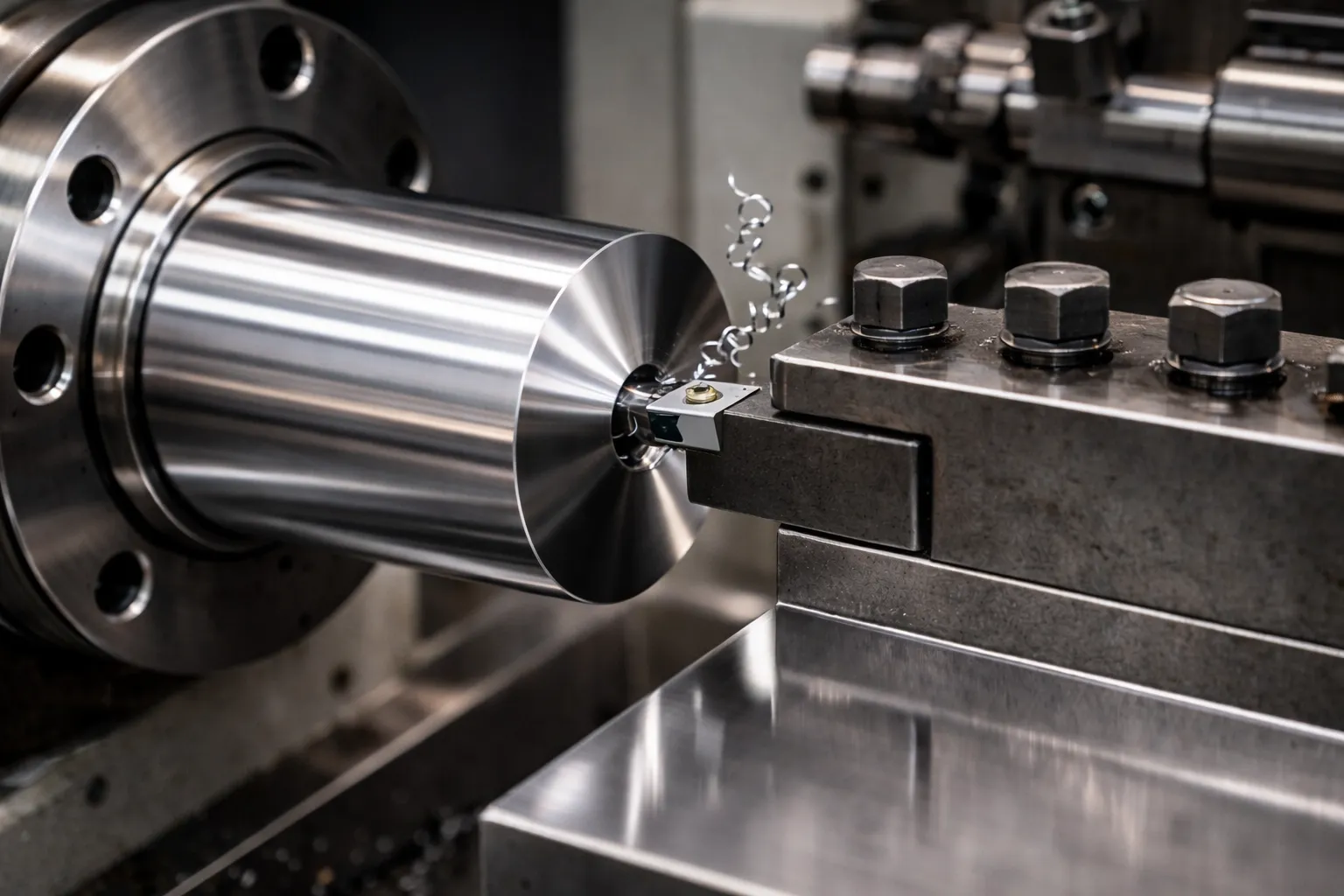
Step 3 – Material removal: chip formation
As the rotating workpiece contacts the cutting edge, a shear zone forms ahead of the tool. Material deforms plastically and breaks away as a chip – continuous, segmental, or fractured – depending on material ductility, tool geometry, cutting speed, and feed rate. This chip-forming process happens continuously at the tool-workpiece interface, removing precise amounts of material per revolution of the spindle.
Step 4 – Precision control: the feedback loop
On manual lathes, precision depends on operator skill, machine condition, and dial indicator feedback. On CNC lathes, closed-loop servo control, in-process gauging, and thermal compensation maintain dimensional accuracy and repeatability across entire production batches. The result: CNC turning can reliably hold ±0.01 mm tolerances in production, with capable machines reaching ±0.005 mm.
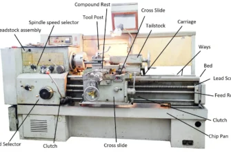
Main Parts of a Lathe Machine
Understanding each component tells you where accuracy problems originate, what maintenance prevents them, and what to inspect when buying a used machine.
The Bed
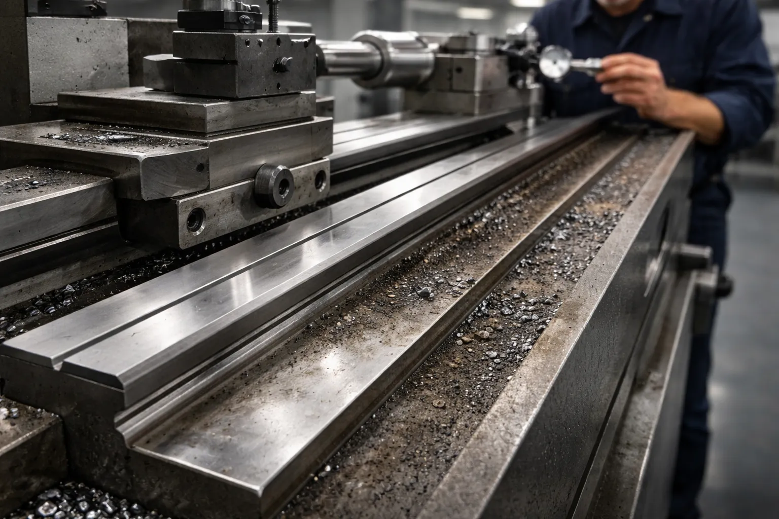
The bed is the spine of the lathe – a long, heavy, precision-cast iron or steel base that supports all other components and defines their alignment. It features hardened and ground ways (flat or V-type guideways) along which the carriage and tailstock slide.
Why it matters for accuracy: Wear in the bed ways directly causes taper in turned parts and is the primary cause of long-term accuracy degradation in high-production lathes.
Common mistakes:
- Not leveling and anchoring the lathe at installation, causing permanent bed twist
- Allowing chips and abrasive swarf to accumulate on ways, accelerating wear and creating stick-slip motion during feeds
The Headstock
The headstock is mounted at the left end of the bed and houses the spindle assembly, bearings, gearbox or belt drive system, and speed controls. The spindle is the rotating output that drives the workpiece through a chuck, faceplate, or collet.
Why it matters for accuracy: Headstock rigidity and spindle bearing quality determine roundness, surface finish, and thermal stability – critical in aerospace and medical turning where form tolerances are specified in microns.
Common mistakes:
- Operating with worn spindle bearings, creating runout errors and surface chatter
- Incorrect chuck mounting or dirty spindle nose causing concentricity loss
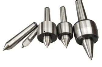
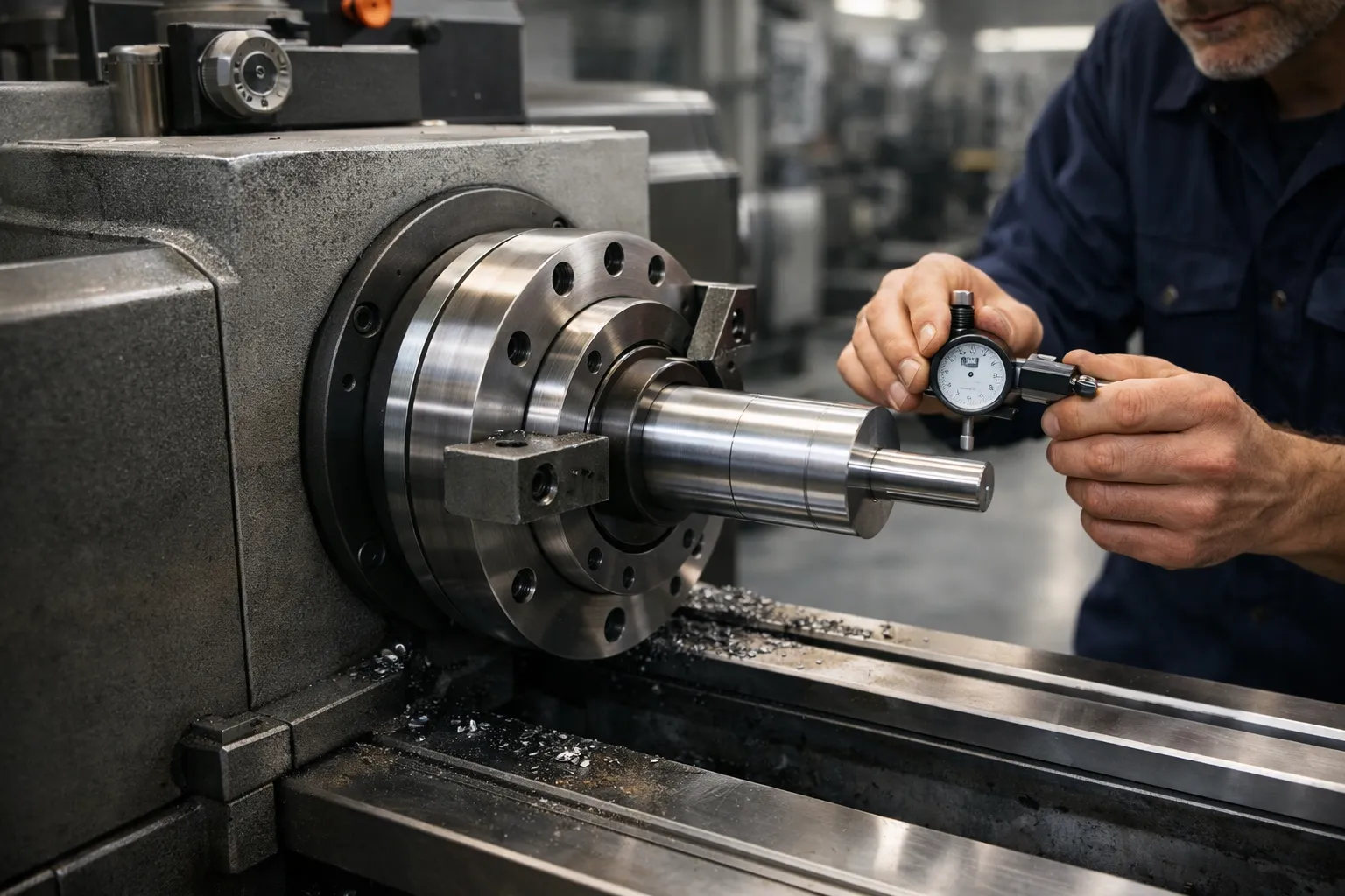
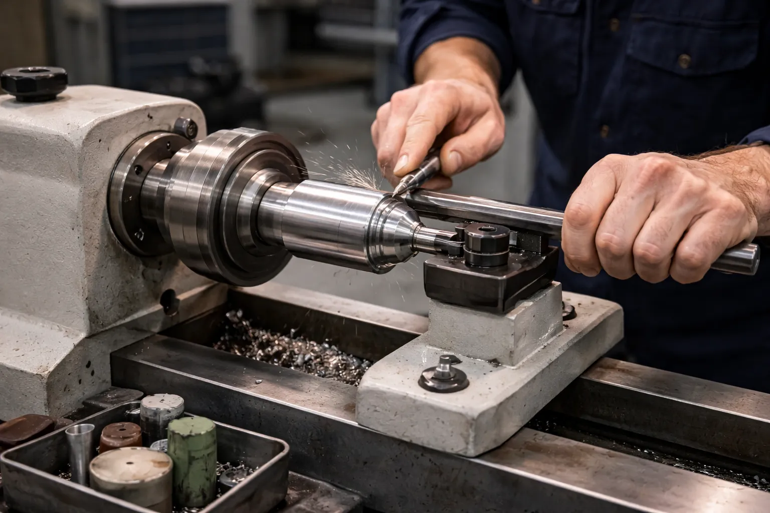
The Tailstock
The tailstock slides on the bed ways opposite the headstock and provides support for the free end of long workpieces via a dead or live center, or holds drilling/boring tooling through its quill.
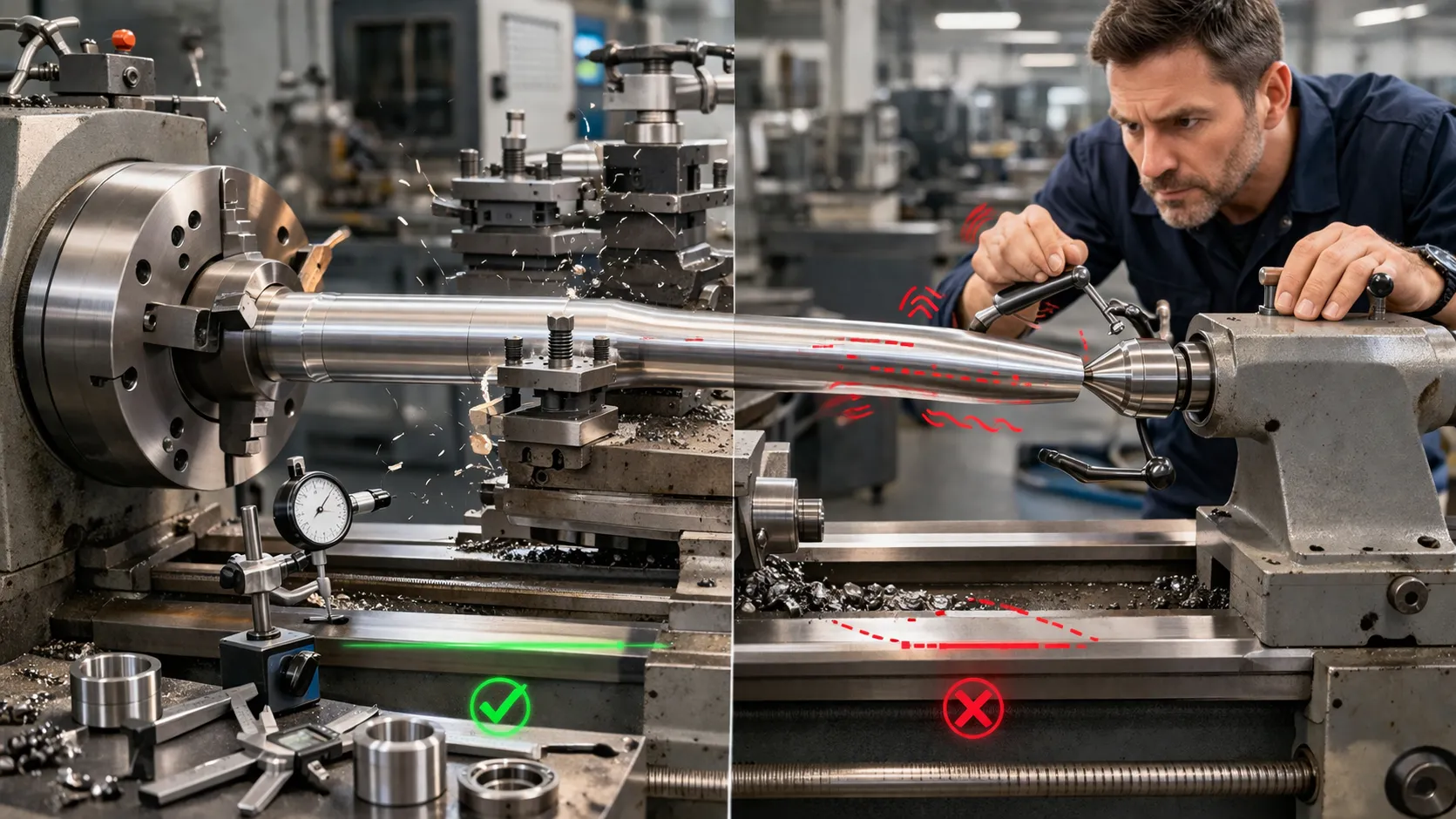
Why it matters for accuracy: Without tailstock support, long slender shafts deflect under cutting forces, producing barrel-shaped profiles and poor surface finish. The tailstock can be offset laterally to cut shallow tapers on manual lathes.
Common mistakes:
- Tailstock misaligned to the spindle axis – creates a taper on parts even when cutting “straight”
- Over-tightening the center into a rotating workpiece generates heat and scoring at the center hole
The Carriage (Saddle, Cross Slide, Compound Rest)
The carriage is the moving tool-holding assembly that rides along the bed ways. It contains the saddle (rides on bed), cross slide (moves in X for diameter), compound rest (pivots for angles and threading leads), and tool post.
Why it matters for accuracy: Backlash and play in any slide directly produces dimensional scatter, poor thread quality, and taper. Gib adjustment – tightening the slide gibs to remove play without introducing friction – is one of the most important maintenance tasks on a manual lathe.
Common mistakes:
- Loose gibs causing chatter, especially on finishing cuts and threading
- Dirty or scored slide surfaces creating non-linear feed motion
The Chuck (Workholding System)
The chuck attaches to the spindle face and grips the raw workpiece for all cutting operations. Major types:
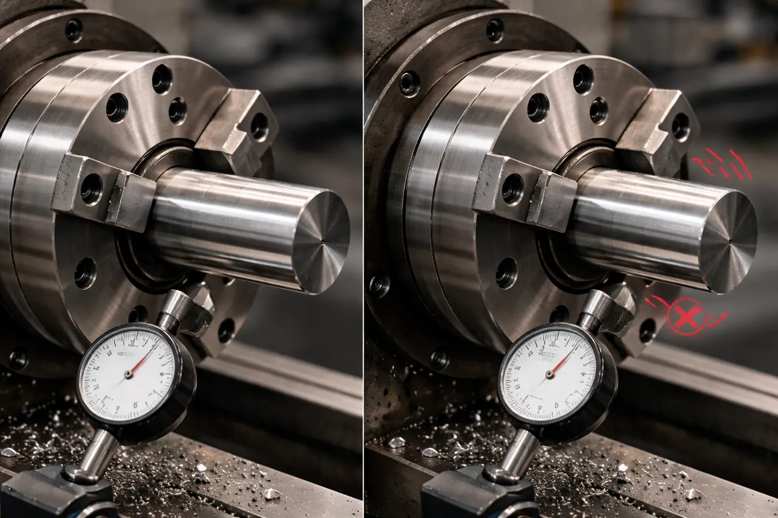
Why it matters for accuracy: Runout in the chuck is runout in the part. A worn or dirty 3-jaw chuck with 0.15 mm runout cannot produce a concentric part without indicating in, regardless of how rigid the rest of the machine is.
Common mistakes:
- Using a chuck with worn jaws on tight-tolerance work
- Insufficient grip on short parts – rule of thumb: grip at minimum 3× the jaw depth
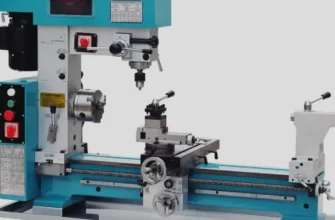
Types of Lathe Machines (Decision-Focused)
The right lathe depends entirely on your production volume, part complexity, required precision, and available budget. Here is how to think about each type in terms of real purchasing and process decisions.
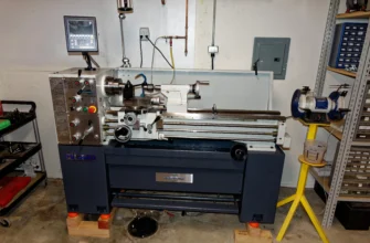
Engine (Center) Lathe
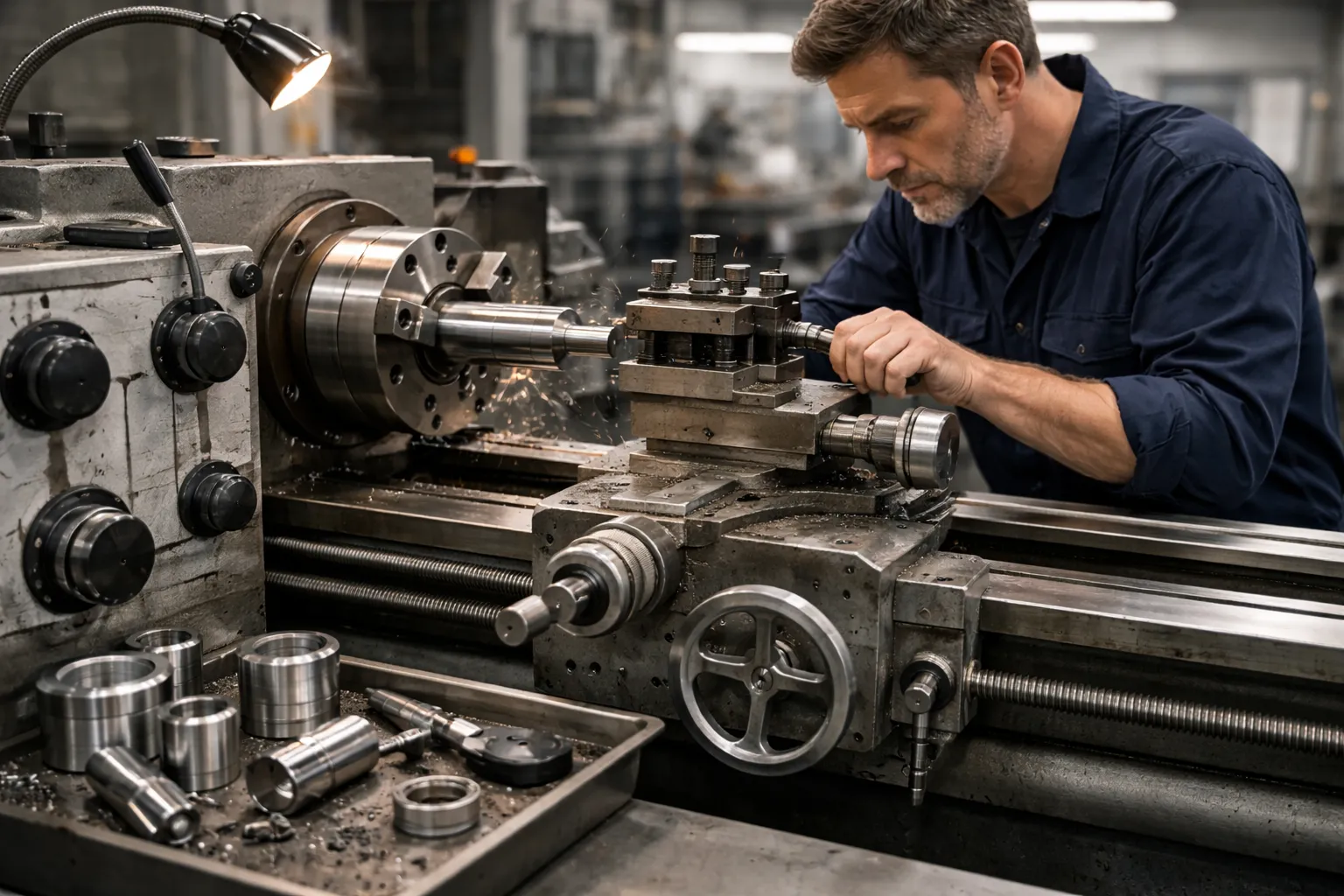
The engine lathe is the classic general-purpose metal lathe found in toolrooms, maintenance shops, and job shops worldwide. A manual machine controlled by handwheels and power feed, with gearboxes for threading and feed rate selection.
- Best for: One-offs, repairs, prototype turned parts, mixed work with no repeat pattern
- Pros: Low entry cost ($5,000–$50,000 new), maximum versatility, low programming overhead, good for training machinists
- Cons: Requires skilled operator at all times, no automation, limited repeatability, slow for volume production
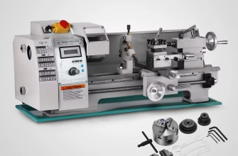
CNC Lathe (CNC Turning Center)
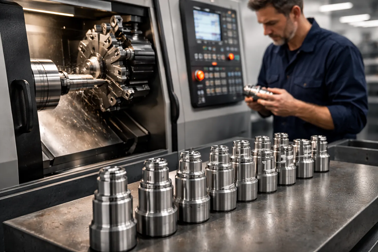
A CNC lathe replaces manual handwheels with servo-driven X and Z axes controlled by a CNC controller running G-code. Live-tooling variants add driven milling and drilling capability for mill-turn operations.
- Best for: Volume production, high-precision parts, complex profiles, unattended running
- Pros: High consistency, fast cycle times, lower cost per part at volume, complex geometry capability
- Cons: Higher capital cost ($30,000–$250,000+), requires CNC programming skills, setup-heavy for single-piece runs
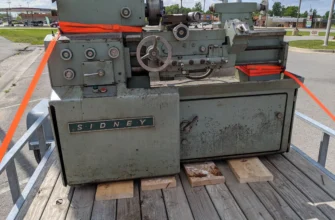
Turret Lathe
The turret lathe replaces the standard tailstock with a hexagonal or octagonal turret that pre-indexes multiple tools for sequential operations without manual tool changes. A semi-automatic production machine.
- Best for: Medium to high volume runs of similar part families, repetitive multi-operation work
- Pros: Faster than engine lathe for families of parts, less costly than CNC, reduced tool change time
- Cons: Less flexible than CNC, limited to part families it was tooled for, requires skilled setup
Speed Lathe
The speed lathe is a high-spindle-speed, lightweight machine with minimal mechanical structure – essentially a rotating spindle and hand rest.
- Best for: Wood turning, polishing, buffing, ornamental work, light metalwork
- Pros: Very simple, low cost, high RPM for finishing operations
- Cons: No power feed, no gearbox for threading, entirely hand-controlled – not suitable for precision metal machining
Machine type comparison
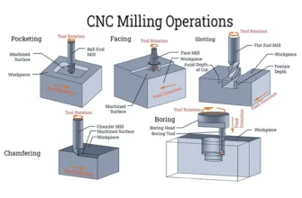
Lathe Operations (The Complete Reference)
These are the seven foundational turning operations. Every turned part is made by combining one or more of these processes.
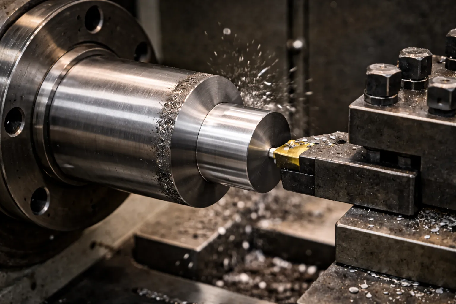
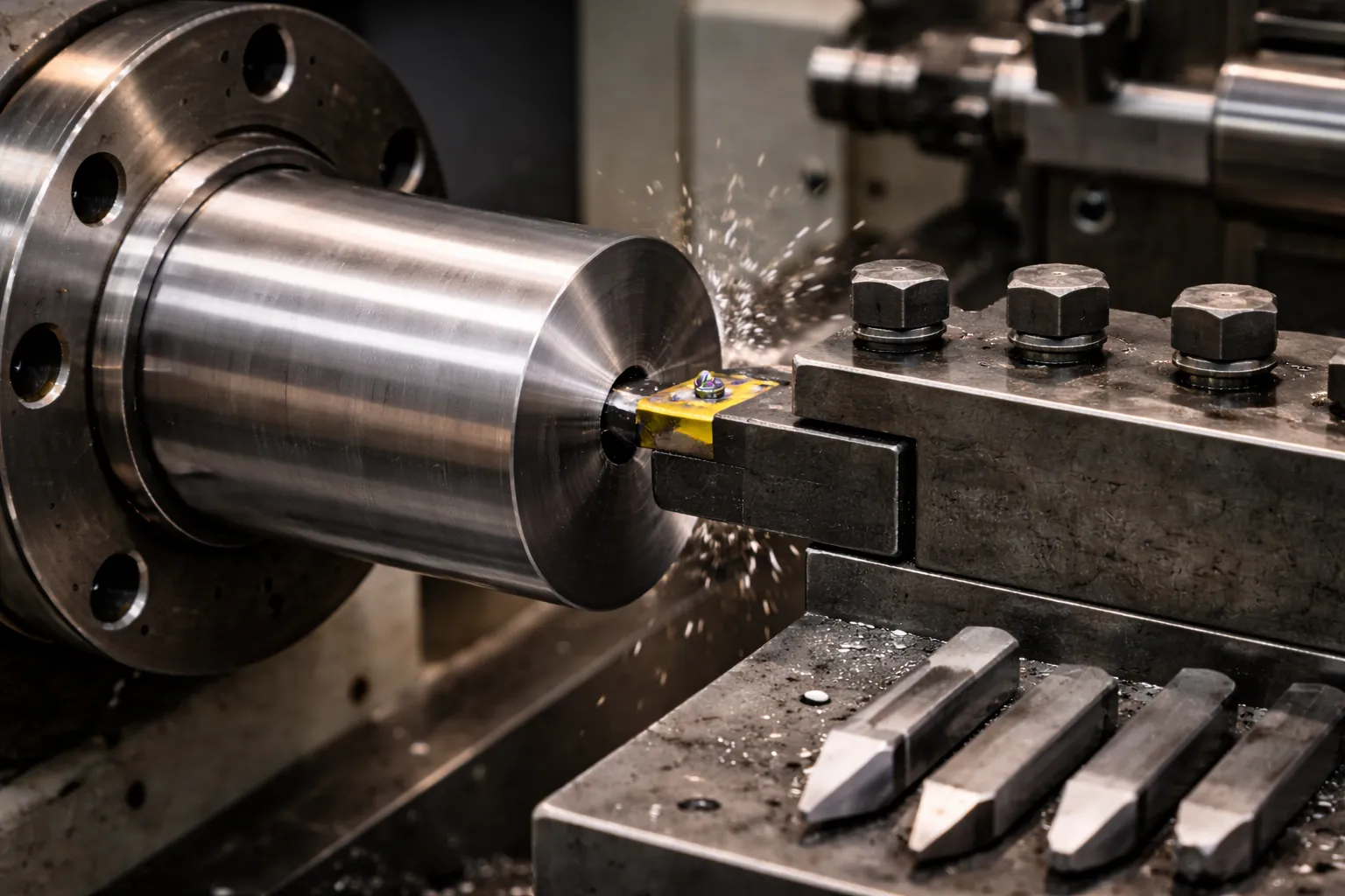
Turning
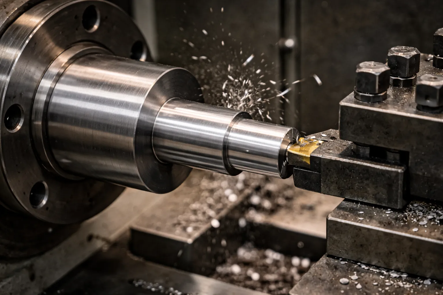
What it does: Reduces the outer diameter (OD) of a rotating cylindrical workpiece to a precise target dimension – either as a straight cylinder, stepped shaft, taper, or free-form profile.
When used: Anytime you need to size a shaft, pin, roller, bushing, or any cylindrical OD feature. It is the most common single operation on a lathe.
Example: Turning a 60 mm diameter steel bar to 50 mm over 300 mm length for a drive shaft, in two passes – a roughing pass removing 4.5 mm radial stock, then a finishing pass removing the remaining 0.5 mm to final size and surface finish.
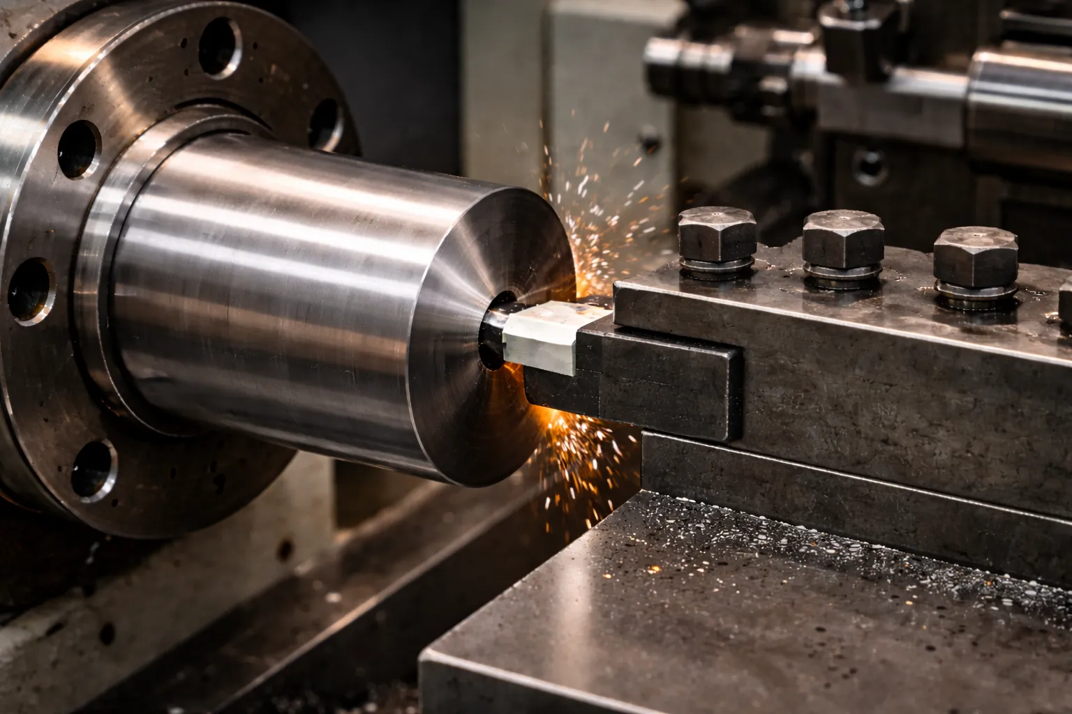
Facing
What it does: Produces a flat surface perpendicular to the axis of rotation at the end of the workpiece, by feeding the cutting tool radially across the face.
When used: To square bar ends before subsequent operations, set accurate part length, create sealing faces, and establish reference surfaces for downstream machining.
Example: Facing both ends of a rough aluminum casting to create flat, square reference surfaces before turning the OD and boring the bore.
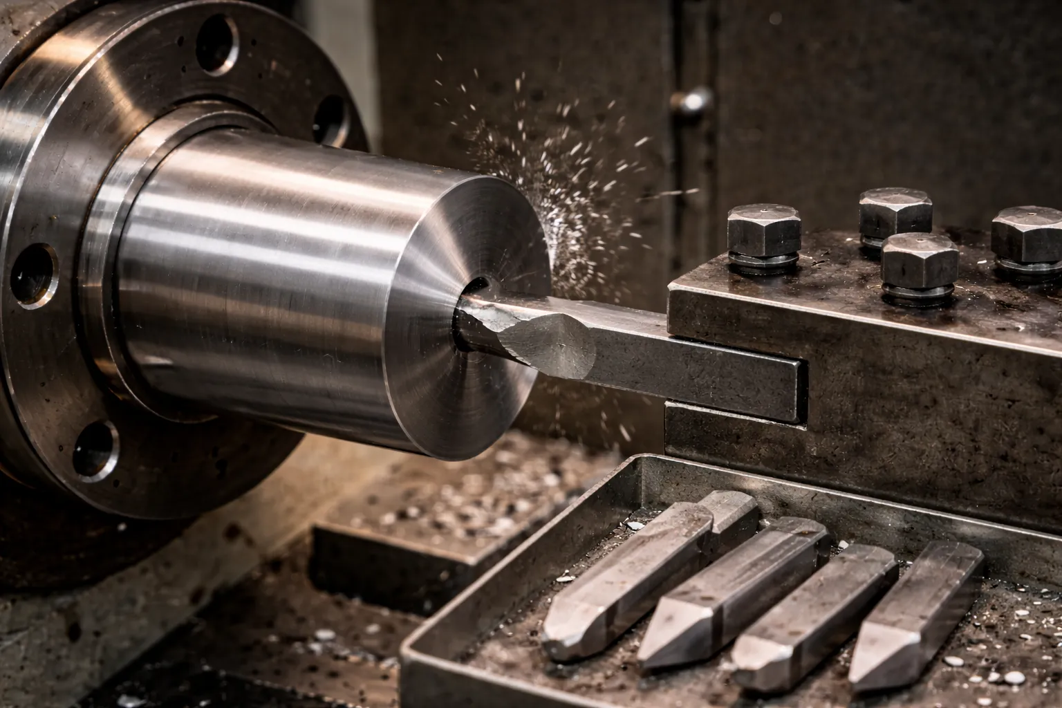
Drilling
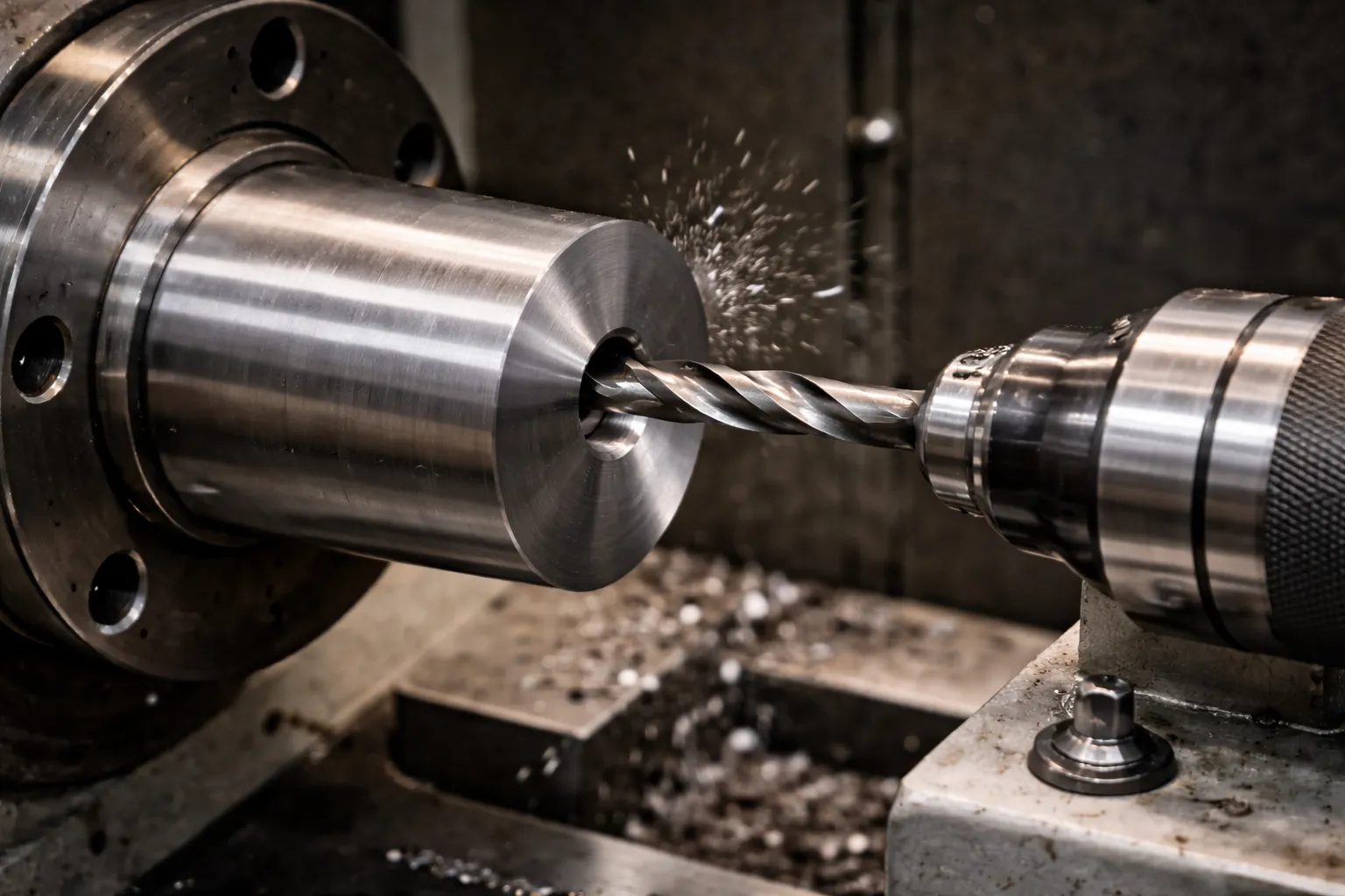
What it does: Creates a cylindrical hole along the spindle axis by feeding a twist drill into the rotating workpiece via the tailstock quill or turret.
When used: To start internal features – bores, threads, blind pockets – especially when the workpiece has no pre-existing hole. Center drilling first establishes a precise starting point for larger drills.
Example: Center-drilling then drilling a 19 mm through-hole in a 50 mm diameter steel hub before boring and reaming to 20H7.
Boring
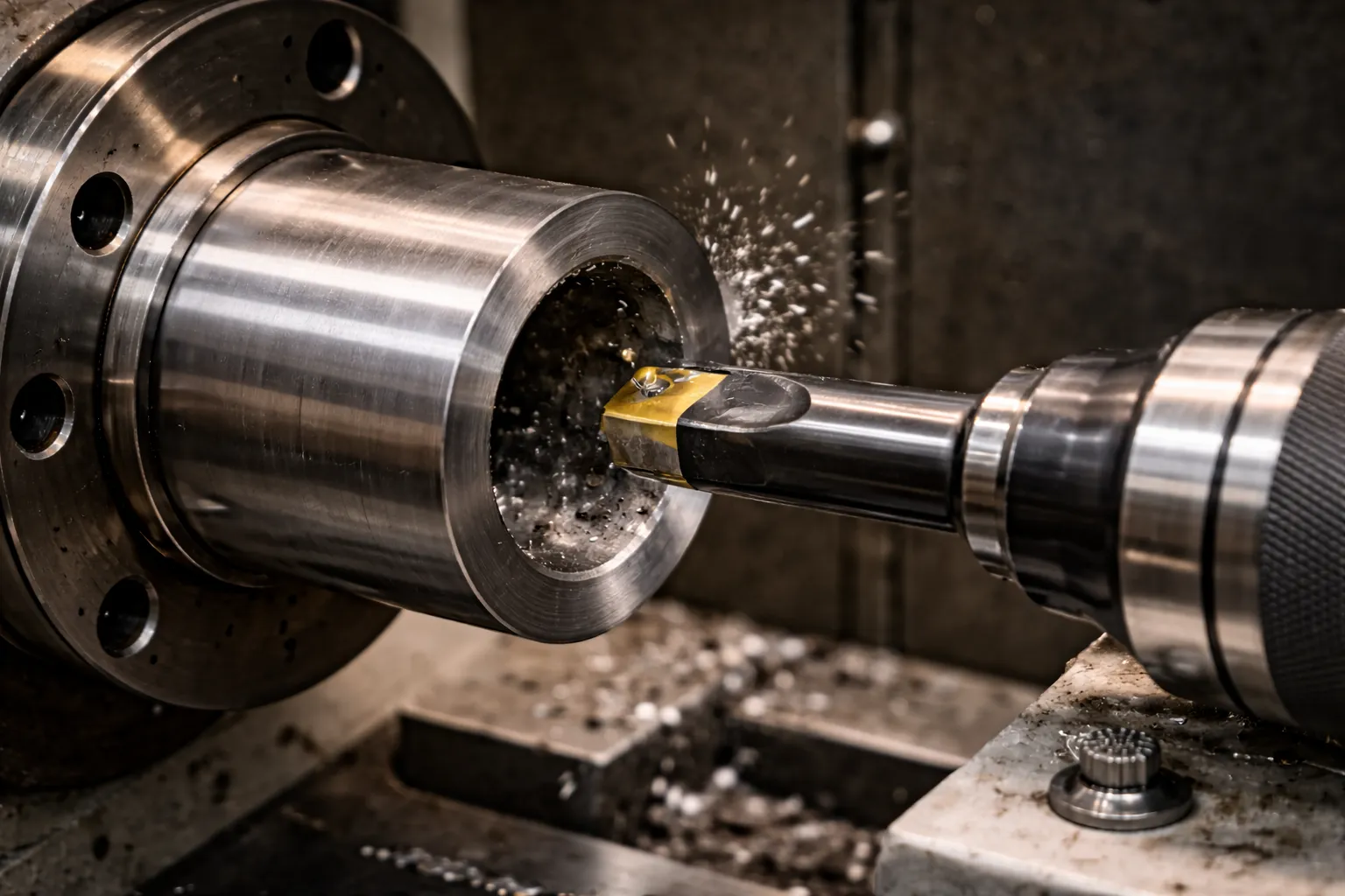
What it does: Enlarges, straightens, and finishes an existing drilled or cast hole using a single-point boring bar, achieving accuracy in size, location, roundness, and surface finish that drilling alone cannot deliver.
When used: Whenever a hole needs tight tolerance (IT6–IT7), true location, or surface finish better than Ra 3.2 μm – engine cylinder bores, hydraulic cylinder bores, bearing housings.
Example: Boring an engine cylinder from a rough bored 79.5 mm to a final 80 mm +0.01/–0 mm with Ra 0.8 μm, after coarse drilling to 78 mm.
Key distinction: Boring corrects hole position errors; reaming only improves surface finish and sizing – use boring when the hole must be straight and located, not just smooth.
Threading
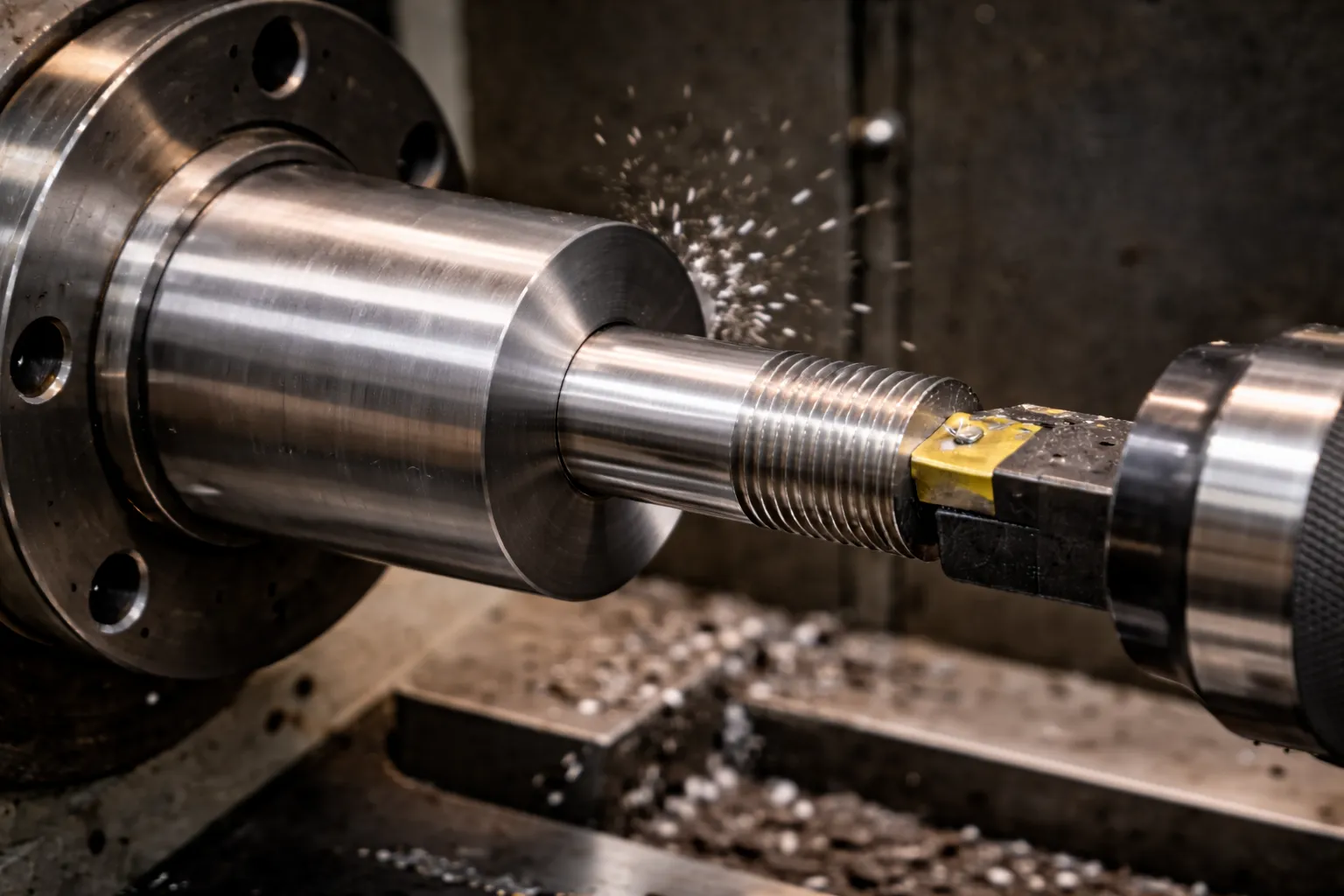
What it does: Cuts a helical groove (external or internal) to create threads for mating with fasteners, couplings, or pipe fittings. Single-point threading on a lathe allows any thread form, pitch, or lead angle – metric, imperial, Acme, trapezoidal, BSPT, NPT.
When used: For custom threaded shafts, studs, adapters, pipe threads, and fine-pitch precision leadscrew threads that standard taps and dies cannot cut.
Example: Cutting an M24×2.0 fine-pitch external thread on a hydraulic rod, using a carbide threading insert over multiple spring passes to eliminate deflection and achieve full thread form.
Knurling
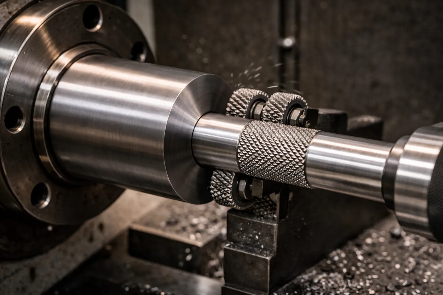
What it does: Cold-forms a patterned texture – typically straight, diagonal, or diamond cross-hatch – onto a cylindrical surface by pressing hardened knurling wheels against the rotating workpiece. Unlike cutting, knurling displaces material without removing it, slightly increasing OD.
When used: To add grip to handles, thumbscrews, adjustment knobs; to create interference-fit surfaces where a slight OD increase improves press-fit retention; for aesthetic surface patterns.
Example: Knurling the grip section of a micrometer thimble or machined handle to a 0.8 mm diamond pattern for ergonomic feel and non-slip function.
Parting (Cut-Off)
What it does: Uses a narrow form tool (typically 2–4 mm wide) to cut completely through the workpiece, separating the finished part from bar stock or cut a groove at a precise diameter.
When used: At the end of a turning cycle on bar-fed CNC lathes and manual lathes to free the completed part, or to cut deep grooves and undercuts for retaining rings and seals.
Example: Parting off a completed 35 mm diameter bushing after all turning, boring, and threading operations, leaving a 0.2 mm face stock for final length grinding if required.
Critical caution: Parting is the most demanding lathe operation. A narrow unsupported blade at full workpiece radius creates severe cutting forces – cutting fluid, sharp inserts, correct feed rate, and maximum rigidity are all non-negotiable.
Lathe Cutting Tools: The Deep Authority Section
The cutting tool is the only part of the system that touches the workpiece. Wrong tool selection costs you surface finish, tolerance, tool life, and margin – often all four simultaneously.
Tool types by function
Tool materials: full comparison
High-Speed Steel (HSS)
HSS tools are tough, fully resharpable, and tolerant of interrupted cuts and variable setups. They perform best at low to moderate cutting speeds (up to ~30 m/min for steel) and are the standard for training, job shops, and non-ferrous light cutting.
- Best for: Prototype work, wood, aluminium, low-carbon steel at low volumes
- Performance limit: Rapid wear above ~50 m/min; unsuitable for hardened materials or high-production speeds
Carbide (cemented carbide, coated carbide)
Carbide tools are 3–4× harder than HSS, allow cutting speeds of 100–400 m/min depending on grade and coating, and dominate volume production in steel, stainless, and cast iron. Modern coated carbide inserts (TiN, TiAlN, AlCrN coatings) resist heat, reduce friction, and extend tool life significantly over uncoated grades.
- Best for: Steel, stainless, cast iron, inconel, titanium at medium to high volumes
- Key advantage: Predictable and consistent tool life – critical for unattended CNC turning
Ceramic tools
Ceramic tools (Al₂O₃ or Si₃N₄ based) tolerate very high temperatures, enabling cutting speeds of 300–1000 m/min in finishing cuts on hardened steels and gray cast iron. They are brittle – interrupted cuts and thermal shock cause edge fracture.
- Best for: Hard turning (50+ HRC) and finishing of cast iron at very high speeds
- Risk: Brittle in interrupted cuts; requires rigid setup and no coolant in some applications
Cermets
Cermets (ceramic-metal composites) offer a middle ground: harder than carbide with better toughness than full ceramics, excellent for finishing cuts at high speeds with outstanding surface finish and edge retention.
CBN (Cubic Boron Nitride)
CBN is used to hard-turn hardened steel (50–65 HRC) at high speeds, replacing grinding in many applications – bearing races, gear components, hardened shafts. Very high cost but unmatched performance in hardened ferrous materials.
PCD (Polycrystalline Diamond)
PCD is used to machine aluminum alloys, copper, carbon fiber, and other non-ferrous/abrasive materials at extremely high speeds with ultra-fine surface finish. PCD is destroyed instantly on ferrous materials – never use PCD on steel.
Tool material selection matrix
Mistakes beginners make with lathe tools
- Running HSS at carbide speeds: HSS discolors blue and loses hardness within seconds – if the chip turns blue-black, the speed is too high.
- Continuing with a chipped or worn insert: A dull cutting edge dramatically increases radial cutting force, causes dimensional drift, and worsens surface finish – yet the most common response is to “push through it.”
- Setting the tool tip off-center: Tool tip above or below the workpiece centerline changes the effective rake angle, increases cutting force, and causes taper and poor finish – always verify center height before starting.
- Ignoring chip management: Stringy chips wrapping around the workpiece or chuck jaw cause surface damage, catch fire risk, and can pull the workpiece out of the chuck – choose the correct chipbreaker geometry for the material and feed rate.
- Wrong insert grade for the application: Using a positive-geometry finishing insert for roughing leads to edge fracture; using a tough negative-geometry rougher for finishing leaves poor surface quality.
Applications of Lathe Machining: Where It Really Matters
Lathe machining is not a general-purpose convenience – in specific industries it is structurally non-negotiable.
Automotive
Every internal combustion engine, transmission, and driveline assembly contains multiple turned parts. Crankshafts, camshafts, wheel hubs, brake drums, gearbox shafts, differential pinions, and CV joint components are all produced by turning.
Real scenario: A Tier-1 automotive supplier producing gearbox shafts runs 5-axis CNC turning centers with bar feeders and automated gauging, achieving Cpk > 1.67 on critical bearing journal diameters – a standard impossible to meet on manual lathes at volume.
Business use case: Upgrading from manual lathes to CNC turning centers delivers a 60% lower cost per part at scale through reduced labor, lower scrap, and automation – and unlocks OEM supplier qualification programs that require process capability documentation.
Aerospace and Defense
Aerospace components demand the highest combination of dimensional precision, material traceability, and surface integrity of any industry. Turbine shafts, landing gear components, hydraulic valve bodies, missile body sections, and structural fasteners are all turned from high-performance alloys – Inconel 718, Ti-6Al-4V, 17-4PH stainless, aluminum 7075.
Real scenario: A CNC lathe turning a Ti-6Al-4V aerospace shaft uses specialized coated carbide tools with low cutting speeds (60–80 m/min), high coolant pressure, and strict thermal management protocols to avoid work-hardening and maintain surface integrity under FAA and AS9100 audit requirements.
General Manufacturing and Energy
Pumps, compressors, hydraulic cylinders, valve bodies, pressure vessel nozzles, and flanges are standard turned products in the oil, gas, power generation, and fluid handling industries. Large-bore CNC lathes and vertical turning centers (VTCs) handle components up to several meters in diameter.
Real scenario: An oil and gas equipment manufacturer turns 316L stainless steel pump shafts on CNC lathes with live tooling, combining turning, drilling, and milling in a single setup – eliminating fixtures, reducing handling errors, and halving lead time versus separate-operation machining.
Medical Devices and Implants
Orthopedic implants (bone screws, tibial trays, femoral stems), surgical instruments, and dental components are turned from biocompatible materials – titanium, cobalt-chrome, PEEK – to tolerances and finishes meeting ISO 13485 and FDA 21 CFR Part 820 requirements.
Real scenario: Medical bone screw threads are cut on CNC lathes with single-point threading tools to ensure root radius, flank angle, and pitch meet ASTM F543 – thread grinding and milling cannot achieve the combination of form accuracy and throughput that CNC turning delivers.
Custom Parts and Prototype Shops
Job shops and prototype facilities use engine lathes and small CNC lathes to produce one-off parts, replacement components, and engineering samples. The lathe remains the fastest route from bar stock to a dimensionally correct turned part for quantities of 1–25 pieces.
Repair and Maintenance Engineering
Industrial maintenance teams use lathes to regrind worn journal surfaces, re-thread stripped fastener holes, produce non-catalog bushings and spacers on-site, and salvage expensive components that would otherwise require full replacement. The value of a lathe in a maintenance operation is measured in avoided downtime cost, not just part cost.
Manual vs. CNC Lathe: The High-Value Decision Block
This is the decision most buyers and plant engineers struggle with. Here is the honest, practical comparison.
Full comparison
When to choose manual
- You produce less than 50 pieces of any given part, with no repeat forecast
- Work is highly varied with no recurring part families
- You are a maintenance or toolroom operation where flexibility and quick setups outweigh per-part efficiency
- Budget is constrained and you cannot justify CNC capital expenditure on current revenue
When to choose CNC
- You have repeating orders or long-run production of turned parts
- Your parts require tolerances tighter than ±0.02 mm or surface finishes better than Ra 1.6 μm consistently
- You need to document and prove process capability (Cpk) to OEM customers
- You want unattended or lights-out production to improve output without proportional labor cost increases
How to Choose a Lathe Machine (Commercial Intent Guide)
Whether you are buying your first lathe or upgrading, this section gives you the decision framework engineers and plant managers use.
Step 1 – Define your workpiece envelope
The two most important physical specs are swing over bed (maximum workpiece diameter) and distance between centers (maximum workpiece length). Size both to your largest anticipated part plus 20–30% headroom.
Step 2 – Establish your production volume and part mix
- Low volume, high mix (1–50 pcs, many part types): Engine lathe or entry-level CNC with quick-change tooling
- Medium volume, recurring mix (50–500 pcs): CNC lathe with bar feeder consideration
- High volume, stable families (500+ pcs): Multi-turret or multi-spindle CNC turning center with automation
Step 3 – Specify your tolerance and finish requirements
- Commercial tolerances (±0.1 mm, Ra 3.2 μm): Any rigid manual or entry CNC lathe
- Precision tolerances (±0.01–0.02 mm, Ra 0.8–1.6 μm): Precision-grade CNC lathe with thermal management
- High precision (±0.005 mm, Ra < 0.4 μm): Precision/ultra-precision turning center with hydrostatic bearings or similar
Step 4 – Assess material requirements
- Aluminum / non-ferrous: Any lathe with adequate spindle speed (2,000+ RPM) and rigidity
- Steel and stainless: Standard CNC lathe, good coolant system essential
- Hardened steels / exotics (Ti, Inconel): High-rigidity CNC lathe with high-pressure coolant and vibration-damping tooling
Step 5 – Evaluate rigidity and machine weight
In industrial lathes, mass equals stability. A heavier, more rigid machine vibrates less under cutting force, holds tolerances over time, and allows deeper cuts – which is why many older well-built industrial lathes still outperform lighter modern imports.
Step 6 – Factor in total cost of ownership (TCO)
Initial purchase price is 40–60% of 5-year TCO for a CNC lathe. Include:
- Tooling, fixturing, and programming setup
- Maintenance and spindle overhaul reserves
- Training and operator qualification
- Floor space and utilities
- Spare parts availability and service response from the manufacturer
Common Mistakes and Safety: What Costs You Parts, Money, and Safety
Costly technical mistakes
- Wrong speeds and feeds: Running too fast burns the tool and work-hardens the surface; running too slow creates built-up edge on the insert and terrible surface finish. Use the manufacturer’s data or cutting speed tables for each material-tool combination.
- Improper workholding: Short grip length, wrong chuck type for the part geometry, or insufficient clamping force leads to workpiece movement during cutting – causing out-of-tolerance parts, tool breakage, and ejection risk.
- Skipping pre-operation inspection: Not checking chuck jaw condition, tool tip center height, tailstock alignment, and slide play before starting results in scrap on the first part – not discovered until after the setup is complete.
- Neglecting machine maintenance: Ways without oil, slideways with chips and grit, and unchecked gib adjustment accelerate wear and destroy the machine’s ability to hold tolerance.
- Poor tool management on CNC: Running past recommended tool life to “save cost” on inserts costs significantly more in scrap parts and potential spindle/chuck damage than the inserts saved.
Non-negotiable safety rules
The lathe is one of the most hazardous machine tools in a shop because rotating parts, high cutting forces, and sharp chips coexist in close proximity to the operator.
- Never wear gloves, rings, watches, loose clothing, or dangling jewelry near a lathe – rotating parts catch and pull loose items with fatal force in milliseconds.
- Tie back long hair – the same entanglement risk applies.
- Always remove the chuck key before starting the spindle – a chuck key left in the chuck becomes a lethal projectile.
- Never measure, clean, or touch a rotating workpiece – stop the spindle completely, confirm it has stopped, then measure.
- Do not make heavy cuts on long slender workpieces without tailstock or steady rest support – deflection can cause the part to bend and eject from the chuck.
- Wear safety glasses or a face shield at all times when the machine is running – chips travel at cutting speed and are thermally hot.
- Keep emergency stop accessible and know the stop procedure – in an emergency: E-stop button first, then main switch.
FAQ
What does a lathe machine do?
A lathe machine rotates a workpiece about its central axis while a cutting tool removes material to produce cylindrical, tapered, threaded, or profiled shapes. It performs operations including turning (OD sizing), facing (flat ends), drilling (axial holes), boring (internal precision holes), threading (helical grooves), knurling (texture), and parting (cut-off). The lathe is the foundational machine tool in metal manufacturing, used across automotive, aerospace, energy, and medical industries.
What are lathe operations?
The seven primary lathe operations are: turning (reducing outer diameter), facing (flattening an end), drilling (axial hole making), boring (internal hole precision finishing), threading (helical thread cutting), knurling (surface texturing by cold-forming), and parting (cut-off from bar stock). Complex parts typically combine several of these operations in a single setup.
What can you make with a lathe?
A lathe can produce: shafts, pins, and axles; bushings and sleeves; flanges and discs; screws and threaded rods; valve bodies and hydraulic cylinders; engine crankshafts and camshafts; bearing housings; surgical implants and dental components; tool handles; and any rotationally symmetric component in metal, plastic, or wood. Modern multi-axis CNC lathes also produce asymmetric and milled features in a single turning setup.
Manual vs. CNC lathe – which do I need?
Choose a manual lathe if you have low volume (under 50 parts), highly varied part types, repair/maintenance work, or a tight budget. Choose a CNC lathe if you have repeating orders, require consistent tolerances tighter than ±0.02 mm, need documented process capability (Cpk), or want to scale production without proportional labor increase. CNC lathes cost $30,000–$250,000 vs. $5,000–$50,000 for manual, but deliver up to 60% lower cost per part at volume.
Is lathe machining expensive?
CNC lathe machining costs $60–$120 per hour of machine time, depending on machine capability and location. For complex 5-axis turning centers, rates reach $150–$250/hr. Manual turning with a skilled machinist runs $25–$40/hr in labor alone. The actual cost per part depends on cycle time, setup amortization, tooling, and material – simple turned parts can cost $5–$30/pc, while complex aerospace components can cost $500–$5,000+. Volume drives cost down significantly; CNC lathes become economically dominant above 50 repeating pieces.
The Question Every Buyer Should Ask
What is actually stopping you from getting precise turned parts without wasting material, budget, or production time?
Most of the time, it is one of these five realities:
- You are unsure whether your tolerances require CNC or can be met on a manual lathe – and the wrong answer costs you either capital investment or scrap rate.
- You do not know which lathe type fits your part family – and buying the wrong machine means paying for capability you cannot use or lacking the capability you need.
- Your current tooling is underperforming, and no one has done a systematic audit of speeds, feeds, and insert grades against your actual materials.
- You are quoting turned parts from external suppliers without knowing their process, and you have no way to validate whether their machines can actually hold the tolerance on the drawing.
- You are scaling production, and manual turning can no longer support the volume – but the CNC investment decision has not been properly justified with a cost-per-part model.
Get Expert Help Matching the Right Lathe Solution to Your Needs
Whether you are:
- Specifying a lathe purchase for a new or expanding facility
- Sourcing turned parts and need to evaluate supplier capability
- Optimizing an existing turning operation for better quality and cost
- Training your team to run lathes to consistent industrial standards
…the details in this guide give you the vocabulary and framework to make confident decisions.
Next steps available to you:
- Request a free consultation on machine selection for your specific part family and volume
- Submit a drawing or technical specification for a turning feasibility and process review
- Ask for a CNC vs. manual cost-per-part analysis using your actual production quantities
- Get a quote for custom turned parts with documented tolerances and material traceability
The right lathe decision, made with full technical context, is one of the highest-ROI choices in any manufacturing or procurement operation. Use this guide as your baseline – and reach out when you are ready to move from knowledge to action.
This guide covers the complete domain of lathe machining – machines, operations, tools, applications, buying decisions, and safety. It is updated to reflect current CNC technology, tooling science, and industrial practice. Bookmark it, share it with your engineering and procurement teams, and return to it when specifications or sourcing decisions require a reliable reference.