What Is a Lathe Machine? Definition, Parts, Working Principle, and Uses
Quick answers:
What Is a Lathe Machine?
Formal definition
A lathe machine is a subtractive manufacturing machine tool in which the workpiece is held and rotated about its longitudinal axis while a single-point cutting tool — mounted on a carriage and advanced by feed mechanisms — removes material to produce the desired shape and dimensions.
The defining characteristic is the rotation of the workpiece (not the tool), which distinguishes it from milling machines and grinders where the tool or wheel rotates against a stationary workpiece.
Why it is called the “mother of all machine tools”
The lathe is historically described as the mother of machine tools because it was the first power-driven machine capable of producing other machine components with sufficient precision to be useful in manufacturing. Before lathes, parts were hand-filed and scraped. The lathe made it possible to produce round, accurate shafts and bores — which in turn made all other machine tools possible.
What shapes and parts it creates
Lathe work produces anything with rotational symmetry about a central axis:
- Shafts, axles, and spindles
- Bushings, sleeves, and spacers
- Flanges, discs, and hubs
- Threaded fasteners and studs
- Valve stems and hydraulic cylinder rods
- Bearing journals and housing bores
- Custom round components in any machinable material
Real-world analogy
Imagine a potter’s wheel: the clay spins, and the potter’s hands shape it. A lathe does exactly this — except the spinning material is metal or plastic, the “hands” are a precision-ground carbide cutting tool, and the control is measured in hundredths of a millimeter. The result is not approximate craft — it is engineering geometry reproduced to specification.
How Does a Lathe Machine Work?
The working process of a lathe can be broken into a clear, sequential workflow. Understanding this workflow helps both beginners and engineers grasp why every major component and setting decision matters.
Step 1 — The workpiece is clamped
The raw material (bar stock, casting, or rough blank) is secured in the chuck mounted on the spindle face of the headstock, or held between the spindle center and a tailstock center for longer workpieces. Correct clamping is the first critical decision: insufficient grip causes the workpiece to slip or vibrate during cutting, destroying tolerance and creating a safety hazard.
Step 2 — The spindle rotates the workpiece
The motor drives the headstock spindle, which rotates the workpiece at a selected RPM. The correct spindle speed depends on the workpiece diameter and the cutting speed recommended for the material-tool combination — for example, aluminum is cut at much higher surface speeds than hardened steel. Too fast and the tool burns; too slow and the tool rubs and work-hardens the surface.
Step 3 — The cutting tool is fed into the material
The cutting tool, clamped rigidly in the tool post on the carriage, is advanced toward the rotating workpiece by moving the cross slide (controlling diameter/depth) and the carriage (controlling length along the part). On a manual lathe, the operator turns handwheels or engages power feed. On a CNC lathe, servo motors move the axes along programmed G-code paths.
Step 4 — Chips are removed
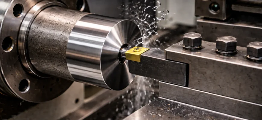
As the rotating workpiece contacts the cutting edge of the tool, a shear zone forms. Material plastically deforms and breaks away as chips — continuous ribbons in ductile materials like aluminum, segmental chips in tougher steels. Cutting fluid is typically applied to cool the interface, lubricate chip flow, and carry chips away from the cutting zone.
Step 5 — The final shape is produced
By controlling the depth of cut (how far the tool engages radially), the feed rate (how fast the carriage moves axially), and the cutting speed (spindle RPM × workpiece circumference), the machinist or CNC program produces the target geometry — diameter, length, taper, thread form, bore diameter — to the specified tolerance and surface finish.
This three-variable control — speed, feed, depth — is the fundamental language of all lathe work.
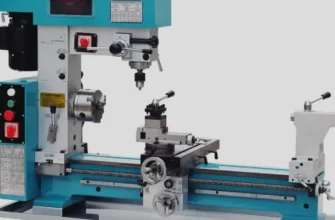
Main Parts of a Lathe Machine
This is where most guides fall short. The parts do not operate in isolation — they form an integrated mechanical system where alignment, rigidity, and adjustment interact directly with part accuracy. Here is how the system actually works together.
The Bed
The bed is the structural foundation of the entire lathe — a heavy, precision-cast iron or welded steel base that supports all other components and defines their geometrical relationship to each other.
The top surface of the bed carries hardened and ground ways — flat or V-type guideways along which the carriage and tailstock slide. The parallelism of these ways to the spindle axis is what ensures that turning produces straight cylinders rather than tapers.
Why it matters for accuracy: Any twist, wear, or misalignment in the bed directly produces taper error in turned parts. A new engine lathe with a bed true to within 0.005 mm/m will hold diameter consistency along the full part length; a worn bed will not — regardless of how precise the rest of the machine is.
Interaction with other parts: The bed is the reference datum for headstock alignment, tailstock alignment, carriage parallelism, and ultimately for every dimension the lathe produces.
The Headstock
The headstock is mounted at the left end of the bed and contains the spindle, bearings, and drive system. The spindle is the heart of the headstock — a precision hollow shaft with a tapered bore (Morse taper or machine taper) at its nose to receive chucks, faceplates, and collets.
Drive systems vary: older engine lathes use back-gear arrangements and stepped pulley drives for speed selection; modern CNC lathes use variable-frequency drives (VFDs) or servo spindle drives with electronic speed control.
Why it matters for accuracy: Spindle bearing quality determines radial runout — any eccentricity in the spindle motion directly appears as roundness error in the workpiece. A headstock with 0.003 mm runout cannot produce a shaft rounder than 0.003 mm, no matter what else you do.
Interaction with other parts: The headstock drives the lead screw and feed rod through a gearbox or feed selector, synchronizing carriage motion with spindle rotation — which is how threads are cut and power feed is engaged.
The Tailstock
The tailstock sits at the right end of the bed and slides along the ways, locking at any position along the workpiece length. Its primary roles are:
- Supporting the free end of long workpieces with a dead or live center, reducing deflection and chatter
- Holding drilling tools (twist drills, reamers, boring bars) via the tailstock quill for axial drilling into the workpiece face
- Providing a slight lateral offset for taper turning
Why it matters for accuracy: Without tailstock support, a 300 mm long shaft of 20 mm diameter will deflect significantly under radial cutting force, producing a barrel-shaped or bowed profile rather than a true cylinder. The deeper the cut, the worse the deflection.
Interaction with other parts: The tailstock must be co-axial with the headstock spindle — any offset between the two centers produces a tapered part. Alignment is checked and corrected by test turning a bar between centers and measuring diameter at both ends.
The Carriage
The carriage is the moving tool platform that rides along the bed ways and carries the cross slide, compound rest, and tool post. It has two primary motions:
- Longitudinal (Z-axis): Moves along the bed parallel to the spindle axis, controlling the cutting length
- Cross (X-axis): Moves perpendicular to the spindle, controlling the diameter (depth of cut)
The carriage is driven manually via a rack and pinion (handwheel) or automatically via the feed rod and apron clutch mechanisms.
Why it matters for accuracy: Play and backlash in the carriage drive and gibs directly cause dimensional scatter, especially when reversing feed direction. Regular gib adjustment maintains smooth, consistent motion.
The Cross Slide
The cross slide sits on top of the carriage saddle and provides transverse (X-axis) motion — movement toward and away from the spindle axis. This is the axis that controls the diameter of the turned feature: advancing the cross slide increases depth of cut and reduces diameter.
The cross slide is driven by its own handwheel with a graduated dial (typically 0.02–0.05 mm per graduation on manual lathes), allowing the operator to control diameter to reasonable precision.
Why it matters for accuracy: Cross slide backlash — the play between the feed screw and nut — means that on manual lathes, the operator must always approach the final dimension from the same direction to avoid dial error from backlash reversal.
The Compound Rest
The compound rest (also called the compound slide or top slide) sits on the cross slide and can be pivoted to any angle relative to the spindle axis. This makes it essential for:
- Cutting short tapers at precise angles
- Setting the thread-cutting lead angle in single-point threading
- Fine infeed during threading passes
The compound rest moves manually only (no power feed) and has a graduated swivel base for angle setting.
Why it matters for accuracy: On a typical engine lathe, the compound rest is the tool’s primary infeed for threading. Its rigidity directly affects thread form quality — a loose compound creates chatter in the thread flanks.
The Tool Post
The tool post is the clamping device on the compound rest that holds the cutting tool at the correct height and angle.
Types of tool posts:
- Rocker-type (old standard): Simple, adjustable for center height, but slow to change tools
- Four-way indexing: Holds four tools, rotates for quick selection
- Quick-change tool post (QCTP): Modern standard — pre-set tool holders click in and out in seconds, with repeatable center height
Why it matters for accuracy: Tool tip height must be exactly on the spindle centerline. A tool set above or below center changes the effective rake angle, increases cutting forces, and produces taper and poor finish. The quick-change tool post is one of the best practical upgrades for a manual lathe because it eliminates center-height resetting on every tool change.
The Lead Screw
The lead screw is a precision threaded shaft running the full length of the lathe bed, driven by the headstock gearbox. It is specifically used for threading operations — when the half-nuts on the carriage apron are engaged onto the lead screw, the carriage is driven at a rate precisely synchronized with spindle rotation, cutting the correct thread pitch.
Why it matters: The lead screw’s accuracy determines the thread pitch accuracy of every thread cut on the lathe. Lead screw wear (common in heavily-used lathes) introduces pitch errors — important to check on used machinery purchases.
Critical distinction: The lead screw is used only for threading. For all other powered feeds (turning, facing, boring), the feed rod is used — keeping the lead screw’s thread clean and unworn.
The Feed Rod
The feed rod is a smooth or keyway shaft, parallel to the lead screw, that transmits power feed motion to the carriage for all turning and facing operations. It drives the apron mechanism to move the carriage longitudinally and the cross slide transversely at controlled feed rates set by the feed selector gears in the headstock.
Why it matters: The feed rod allows consistent, hands-free feeding during long turning passes, producing uniform surface finish across the full workpiece length — something impossible to achieve manually over long distances.
How the parts work together (the complete picture)
When you take a facing cut on an engine lathe, this is the actual system interaction:
- Motor → headstock gearbox → spindle rotates at selected RPM
- Workpiece rotates in chuck attached to spindle
- Operator engages cross-slide power feed via feed rod → apron mechanism
- Carriage cross slide advances at a selected feed rate (mm/rev)
- Tool post holds the cutting tool at center height
- Tool contacts rotating workpiece → chip forms and is removed
- Result: flat, perpendicular face at the end of the part
Every part in this chain is active. If any component has wear, misalignment, or improper setup, the result shows up in the part as taper, chatter, poor finish, or out-of-tolerance dimensions.
Working Principle of a Lathe Machine
The rotation principle — why it is fundamental
The entire productive capability of a lathe depends on the controlled rotation of the workpiece. Rotation does two things simultaneously:
- It continuously presents fresh, uncut material to the cutting edge — the cutting action is nearly continuous, unlike a milling cutter which has interrupted cuts per tooth
- It produces geometric rotational symmetry naturally — whatever the tool’s path relative to the axis, the resulting shape is symmetric about that axis
This is why the lathe excels at shafts, bores, and threads — geometry that is inherently defined by rotation about an axis.
How cutting action happens
Cutting on a lathe is a shear process. As the tool edge contacts the rotating workpiece surface, the material ahead of the cutting edge is compressed until it shears along a slip plane and flows away as a chip. The geometry of this shear zone — and therefore the cutting forces, tool temperature, chip form, and surface finish — depends on:
- Cutting speed (how fast the workpiece surface passes the tool)
- Feed rate (how fast the tool advances per revolution)
- Depth of cut (how deep the tool engages radially)
- Tool geometry (rake angle, clearance angle, nose radius)
- Material properties (hardness, ductility, thermal conductivity)
How feed motion creates shape
The carriage feed motion combined with the spindle rotation creates a helical path of the tool relative to the workpiece. The pitch of this helix is the feed rate (mm/rev). A very fine feed (0.05 mm/rev) creates a dense helix = smooth surface finish. A coarse feed (0.5 mm/rev) creates a visible feed pattern with rougher Ra.
For threading, the feed is synchronized exactly with the spindle rotation via the lead screw so the helical feed path has the exact pitch of the required thread.
Why precision depends on setup, alignment, and rigidity
The lathe is not self-correcting. Every source of error in the mechanical system appears in the workpiece:
- Bed misalignment → taper along the part length
- Spindle runout → roundness error
- Tool tip above center → increased cutting force, poor finish, and effective taper
- Workpiece deflection → barreling on long slender shafts
- Chuck runout → eccentric parts
- Machine vibration / chatter → surface waviness and dimensional scatter
This is why setup — leveling the machine, checking alignments, indicating the chuck, setting tool center height — is not optional. It is the foundation of accuracy.
Types of Lathe Machines
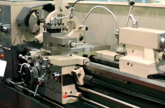
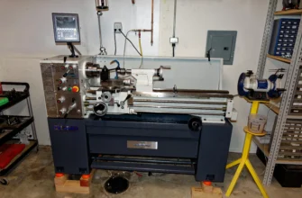
Engine Lathe
The engine lathe is the standard general-purpose metal lathe and the most common type found in job shops, toolrooms, training workshops, and maintenance facilities. It has a full bed, a gearbox for threading and feed selection, a cross slide and compound rest, and is operated manually with handwheels and power feed.
Best for: Prototyping, one-off parts, repairs, mixed one-off machining work, training machinists on lathe fundamentals.
Who uses it: Job shops, maintenance engineers, training institutions, repair workshops.
When to choose it: When versatility and low cost matter more than throughput or automation.
Tool Room Lathe
The tool room lathe is a high-precision version of the engine lathe — built to tighter tolerances, with better surface finishes on its ways and slides, superior spindle bearings, and finer controls. It is designed for precision work in tool rooms — where gauges, jigs, fixtures, molds, and precision dies are made.
Best for: Precision single pieces, tool and die work, gauge making, master parts production.
Who uses it: Tool and die makers, mold shops, gauge rooms, precision engineering facilities.
When to choose it: When workpiece tolerances are tighter than a standard engine lathe can consistently deliver, and production volume is low.
Bench Lathe
A bench lathe is a compact, light-duty lathe mounted on a workbench rather than a floor-standing base. It functions like a small engine lathe but is limited in swing, bed length, and cutting capacity.
Best for: Small parts, instrument-making, hobby machining, watch and clockmaking.
Who uses it: Hobbyists, instrument technicians, small prototyping workshops.
When to choose it: Limited floor space, small part sizes (under 100–150 mm swing), low-power requirements.
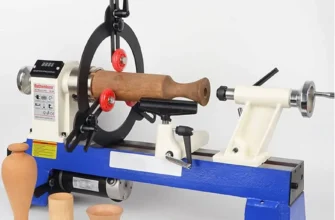
Speed Lathe
A speed lathe is a minimal, high-speed lathe with a simple structure: spindle, two-speed belt drive, and a hand rest for manual tool control. It has no carriage, no lead screw, no cross slide — it is entirely hand-controlled.
Best for: Wood turning, polishing, buffing, ornamental work, very light facing.
Who uses it: Woodworkers, craftsmen, light metalworking for non-precision work.
When to choose it: Only when the work is entirely freehand, light, and non-precision.
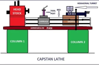
Turret Lathe
A turret lathe replaces the standard tailstock with a rotating hexagonal or octagonal turret that can hold multiple tools pre-set for sequential operations. After each operation, the turret indexes to the next tool — eliminating manual tool changes for families of repeating operations.
Best for: Medium-volume production of parts requiring multiple sequential turning, drilling, and boring operations.
Who uses it: Production shops running repeating part families without full CNC automation.
When to choose it: When you have 100–2,000+ pieces of the same part requiring multiple operations, but CNC investment is not justified.
CNC Lathe (CNC Turning Center)
A CNC lathe replaces manual handwheels with servo-driven X and Z axes controlled by a CNC controller executing G-code programs. Modern CNC turning centers add live-tooling (driven milling/drilling tools in the turret), Y-axis, and bar feeder capability for complete mill-turn operations.
Best for: Volume production, tight tolerances, complex profiles, unattended operation, parts requiring documented process capability.
Who uses it: Production manufacturers, precision component suppliers, aerospace, automotive, and medical subcontractors.
When to choose it: When you have repeating orders, tolerances tighter than ±0.02 mm, or the need to scale without proportional labor increase.
Vertical Lathe (Vertical Turning Center / VTL)
A vertical lathe has its spindle oriented vertically rather than horizontally, with the workpiece rotating on a horizontal faceplate. This configuration makes it ideal for large-diameter, short, heavy parts — where a horizontal lathe would require elaborate support and balancing.
Best for: Large flanges, turbine discs, ring gears, pressure vessel heads, large brake drums — parts too wide and heavy to handle horizontally.
Who uses it: Heavy industry, power generation, shipbuilding, large-scale manufacturing.
When to choose it: When part diameter exceeds 500 mm or part weight makes horizontal clamping impractical.
Common Lathe Operations
Turning
Reduces the outer diameter of the rotating workpiece to a target size, producing straight cylinders, stepped shafts, or contoured profiles. It is the most fundamental and most frequently performed lathe operation.
When used: Sizing any external cylindrical feature — shafts, journals, bosses, diameters.
Result: A precise outer diameter to specified tolerance and surface finish.
Facing
Produces a flat surface perpendicular to the spindle axis at the end of the workpiece by feeding the cross slide radially across the face.
When used: To square bar ends, set accurate part length, create sealing surfaces, and establish reference faces before subsequent operations.
Result: A flat, square end face — the starting point for most turned parts.
Drilling
Creates a cylindrical hole along the spindle axis using a twist drill held in the tailstock quill or turret.
When used: To start internal features in parts before boring or reaming. Center drilling first establishes a precise starting location.
Result: A rough axial hole that is then refined by boring, reaming, or threading.
Boring
Enlarges, straightens, and finishes an existing hole using a single-point boring bar to achieve tight dimensional tolerance, correct location, and surface finish that drilling alone cannot deliver.
When used: Bearing housings, hydraulic cylinders, engine bores — any application requiring a hole to IT6/IT7 tolerance or better.
Result: A precisely sized, straight, well-located internal bore. Key point: boring corrects hole position; reaming only improves surface finish and size on an already-straight hole.
Threading
Cuts a helical groove (external or internal) to create threads for mating with fasteners, couplings, or pipe connections. Single-point threading on a lathe can cut any thread form, pitch, or standard — metric, imperial, ACME, trapezoidal, pipe threads.
When used: Custom threaded shafts, hydraulic fittings, leadscrew threads, fine-pitch threads where standard dies are unavailable.
Result: A geometrically correct thread form of specified pitch, diameter class, and fit.
Knurling
Cold-forms a patterned texture (straight, diagonal, or diamond crosshatch) on a cylindrical surface using hardened knurling wheels pressed against the rotating workpiece. Unlike other operations, knurling displaces material without removing it, slightly increasing OD.
When used: Grip surfaces on tool handles and knobs, interference-fit surfaces, aesthetic patterns.
Result: A textured surface for improved grip or press-fit retention.
Parting (Cut-Off)
Uses a narrow grooving tool to cut completely through the workpiece, separating the finished part from the bar stock.
When used: At the end of turning cycles to free the completed part; also used for deep grooves, undercuts, and retaining ring grooves.
Result: Part separated from bar stock, or a precise deep groove at a specified diameter.
Grooving
Cuts a controlled-width channel (groove) into the outer diameter, face, or bore of a workpiece using a form tool with a specific width.
When used: O-ring grooves, retaining ring grooves, relief grooves before threading, oil grooves in bearing journals.
Result: A groove of specific width, depth, and location.
Taper Turning
Produces a conical surface by angling the tool path relative to the spindle axis. Achieved by:
- Swiveling the compound rest to the taper angle (short steep tapers)
- Offsetting the tailstock laterally (long gradual tapers on manual lathes)
- Taper attachment or CNC linear interpolation (precise tapers of any length)
When used: Morse taper toolholders, valve seats, machine spindle tapers, conical fits.
Result: A precise conical surface at the specified included angle.
What Is a Lathe Machine Used For?
Metalworking (core application)
The lathe is the primary machine tool for all turned metal components. Nearly every precision metal part with a cylindrical feature — shafts, pins, bores, threads — passes through a lathe at some stage.
Automotive manufacturing
Crankshafts, camshafts, drive shafts, wheel hubs, brake drums, transmission gears, and differential components are produced by turning. CNC turning centers run 24/7 in automotive supplier plants, producing critical rotating components to tolerances of ±0.005–0.010 mm.
Aerospace and defense
Turbine shafts, hydraulic actuator rods, landing gear components, and structural fasteners in titanium, Inconel, and high-strength stainless are machined on high-rigidity CNC lathes to AS9100 quality standards. Aerospace turning demands the highest combination of dimensional precision and material traceability.
Medical devices and implants
Orthopedic bone screws, surgical instrument shafts, dental implant abutments, and implantable components are turned from titanium and cobalt-chrome to ISO 13485 requirements. The lathe’s ability to produce smooth surface finishes and tight tolerances on bio-compatible materials makes it irreplaceable in medical manufacturing.
General manufacturing and energy
Pump shafts, hydraulic cylinder rods, valve bodies, pipeline fittings, compressor components, and pressure vessel nozzles are turned in stainless steel, alloy steel, and specialty metals across the oil, gas, and power generation sectors.
Tool room and prototype work
Engine lathes and tool room lathes produce gauges, jigs, fixtures, cutting tools, and prototype parts where one-off precision matters more than throughput. The tool room lathe remains essential for precision engineering shops that build and maintain production tooling.
Repair and maintenance engineering
Lathes allow maintenance teams to salvage worn shafts, re-thread stripped surfaces, manufacture replacement bushings, and produce non-catalog components on-site — avoiding downtime associated with sourcing custom parts.
Woodworking and craft
Speed lathes and wood lathes produce decorative turned woodwork — furniture legs, bowls, spindles, handles — using hand-held tools at high spindle speeds.
Education and training
Engine lathes are the foundational machine in every machining education program. Understanding how to operate a manual lathe correctly — speeds, feeds, tool geometry, setup — builds the engineering intuition required for CNC programming and advanced manufacturing roles.
Manual Lathe vs. CNC Lathe
Choose manual when: Work is mixed, volume is low, flexibility is the priority, and budget is constrained.
Choose CNC when: Parts repeat, tolerances are tight, production needs to scale, or customer quality documentation is required.
Advantages and Limitations of Lathe Machines
Advantages
- Versatility: A single lathe performs turning, facing, boring, threading, drilling, knurling, and grooving without changing the machine — only the tooling changes.
- Precision: CNC lathes routinely hold ±0.005–0.010 mm tolerances and Ra 0.8 μm surface finishes in production.
- Broad material range: Lathes machine metals (steels, aluminum, titanium, copper, brass), plastics, composites, and wood — with appropriate tooling.
- Scalability: From single prototypes on a manual engine lathe to thousands of parts per day on CNC turning centers with bar feeders.
- Cost-effectiveness at volume: Once programmed and set up, CNC lathe cycle times and labor costs drop dramatically compared to manual machining at equivalent quality.
Limitations
- Geometry constraint: A standard lathe excels at rotationally symmetric features. Non-symmetric features (flats, off-axis holes, complex 3D surfaces) require multi-axis CNC or secondary operations on milling machines.
- Skill dependency (manual lathes): The accuracy of a manual lathe is bounded by operator skill, machine condition, and setup quality — consistent tolerance across shifts is difficult without CNC.
- Setup sensitivity: Incorrect tool center height, misaligned tailstock, or bed misalignment directly produces out-of-tolerance parts — the machine does not self-correct.
- High initial investment (CNC): A capable CNC turning center requires $30,000–$250,000 capital investment plus programming, tooling, and training costs.
- Limited to one setup: A standard lathe produces turned features only. Mill-turn CNC centers partially overcome this, but complex prismatic features still require milling operations.
Common Beginner Questions: FAQ
What is a lathe machine in simple words?
A lathe machine spins a piece of material — usually metal or wood — while a sharp cutting tool removes the unwanted parts to create a precise, symmetrical shape. Think of it as the opposite of sculpting: you spin the material and the tool shapes it from the outside in.
What is the working principle of a lathe machine?
The working principle is rotation plus cutting tool feed. The workpiece rotates at a selected speed. A cutting tool is advanced into the rotating surface. Material is removed by the shearing action between the tool edge and the workpiece. By controlling where the tool goes, the speed of rotation, and the feed rate, any cylindrical, conical, or threaded shape can be produced.
What are the main parts of a lathe machine?
The main parts are: bed (structural base and way system), headstock (spindle drive and speed control), tailstock (end support and drilling), carriage (tool-holding platform that moves along the bed), cross slide (radial/depth control), compound rest (angle infeed for tapers and threading), tool post (cutting tool clamp), lead screw (threading drive), and feed rod (power feed for turning and facing).
What is the use of a lathe machine?
Lathes are used to produce shafts, pins, bushings, flanges, threaded fasteners, bores, and any rotationally symmetric component. Applications span automotive (crankshafts, hubs), aerospace (turbine shafts, actuators), medical (bone screws, implants), energy (pump shafts, valves), general manufacturing, repair work, and educational tool room training.
What is the difference between an engine lathe and a CNC lathe?
An engine lathe is a manually operated general-purpose lathe requiring an operator to control all movements by handwheel. A CNC lathe uses servo motors and G-code programs to control all axes automatically, delivering higher repeatability, tighter tolerances, and the ability to run unattended. Engine lathes cost $5,000–$50,000 and suit low-volume varied work; CNC lathes cost $30,000–$250,000+ and deliver their advantage in repeating production runs.
What operations can be done on a lathe machine?
A lathe performs: turning (OD reduction), facing (flat end surface), drilling (axial holes), boring (internal precision holes), threading (helical grooves), knurling (surface texturing), parting/cut-off (separating parts from bar), grooving (channels and undercuts), and taper turning (conical surfaces).
Why is a lathe called the mother of machine tools?
The lathe is called the mother of machine tools because it was the first machine tool capable of producing precision cylindrical parts and components needed to build other machine tools — including lathes themselves. The lathes that made the early Industrial Revolution possible were built using earlier lathes; without the lathe, no other precision machine tool could be manufactured. It is the foundational enabling tool of mechanical engineering and manufacturing.
Conclusion
The lathe machine is not simply a piece of shop equipment. It is the foundational tool of precision manufacturing — the machine that made the modern engineered world possible by enabling the consistent production of accurate cylindrical components.
Understanding the lathe — how the bed, headstock, tailstock, carriage, cross slide, compound rest, tool post, lead screw, and feed rod interact as a system — gives you a framework for understanding all other machining processes, CNC programming logic, and manufacturing quality systems.
Whether you are a student learning lathe fundamentals, a machinist optimizing your lathe work, an engineer specifying a process, or a buyer evaluating a machining supplier — the principles here are the same. Master the lathe, and you understand the language that all precision manufacturing is written in.
The natural next step is understanding CNC turning operations in depth, cutting tool selection by material, and how lathe machining fits into full manufacturing workflows — all of which build directly on the foundation this guide provides.