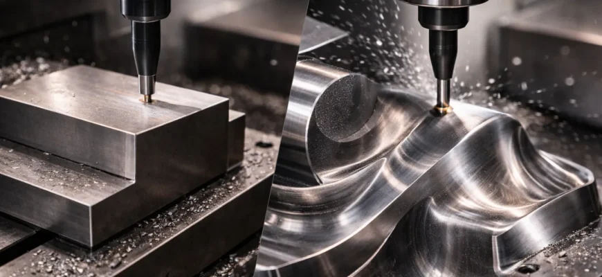
Kellering in machining refers to three-dimensional contour milling — a process in which a cutting tool follows a complex, curved path across a workpiece surface in all three axes simultaneously, removing material to produce precisely shaped non-flat geometry. The term traces directly to the Keller Machine Company, whose tracer-controlled milling systems were the defining technology for complex surface replication in die, mold, and piston manufacturing throughout the twentieth century.
In plain English: When a machinist says “we’re kellering that surface,” they mean the cutter is not moving in simple straight flat passes — it is following a sculpted three-dimensional contour to produce a dome, cavity, freeform curve, or blended surface that cannot be made with conventional flat-path milling.
Quick answers:
What Does Kellering Mean in Machining?
The working definition
Kellering means machining a complex three-dimensional surface by following its contour with a cutting tool — as opposed to milling flat planes, pockets, or stepped features with straight-line passes at fixed depth.
The word describes both a historical legacy and a practical process type. In its original meaning, it referred specifically to operations performed on Keller tracer-milling machines — machines that copied a three-dimensional master model by having a stylus trace the model’s surface while a synchronized cutter reproduced that surface in metal. Over time, “kellering” came to describe the class of work those machines did — complex 3D surface machining — regardless of what machine performed it.
Why it is niche and unfamiliar to many readers
Most modern CNC machining education does not use the word “kellering.” It is not found in standard CAM software menus, CNC programming textbooks, or mainstream machining curricula. Today’s engineers and programmers describe the same operations as 3D contour milling, surface finishing, sculptured surface machining, or free-form CNC milling.
The term “kellering” persists primarily in:
- Legacy shop environments where machinists trained on or alongside Keller equipment
- Die and mold shops with long institutional memory of the Keller era
- Piston and engine component manufacturers where the piston dome milling process was historically performed on Keller machines
- Regional manufacturing cultures — particularly in North American heavy industry — where the Keller brand was dominant
A machinist who uses the word “kellering” is almost certainly communicating real, specific technical knowledge. The gap is simply one of vocabulary generation, not concept.
Important Clarification: Kellering in Machining vs. Other Meanings
The word “kellering” can appear in completely unrelated contexts — as a surname, in regional or cultural references, and in non-manufacturing discussions. This article addresses only the machining meaning.
Why search confusion exists
When someone searches “kellering machining” or “what is kellering,” search results often surface:
- Generic milling content that does not address the specific term
- Knurling content (a phonetically similar word describing a completely different lathe-based process)
- Vague glossary entries that acknowledge the word without explaining it clearly
- Forum posts where the term is used without context
Kellering is not knurling. This point deserves direct emphasis because it is the most common conflation in online search:
| Kellering | Knurling | |
|---|---|---|
| Machine | Milling machine / machining center | Lathe |
| Motion | 3D contoured cutter path | Rolling wheel pressed on rotating workpiece |
| Material action | Removes material (cutting) | Displaces material (cold-forming) |
| Surface produced | Contoured 3D geometry | Textured grip pattern (diamond / straight) |
| Purpose | Shape complex curved surfaces | Create grip, increase OD, decorative texture |
They share no technical relationship. Confusion arises purely from surface-level similarity in the words and the fact that both are somewhat niche machining terms.
For the rest of this article, “kellering” means exclusively the three-dimensional contour milling process described above.
Historical Origin of Kellering
The Keller Machine Company
The Keller Machine Company, based in the United States, produced tracer-controlled milling machines that became the industry standard for complex surface replication in precision manufacturing from the mid-twentieth century. Their machines solved a problem that standard milling technology could not address: how do you accurately reproduce a complex, sculpted three-dimensional surface from a physical master into a steel workpiece?
Before Keller machines, that problem was solved — slowly and expensively — by highly skilled die sinkers who used files, scrapers, grinding stones, and years of experience to hand-fit die cavities to a master form. The process was labor-intensive, inconsistent across shifts and operators, and a significant bottleneck in production tooling lead times.
The tracer mechanism
Keller’s innovation was electromechanical tracer control. The machine operated as follows:
- A physical master model — machined, cast, or hand-sculpted in a relatively soft, machinable material — was mounted on the machine table alongside the actual die block or workpiece
- A tracer stylus — a precision contact probe — rested against the surface of the master with light, consistent pressure
- As the machine moved the stylus across the master in systematic passes, the stylus deflections (caused by the surface rising and falling) were converted into electrical or hydraulic control signals
- Those signals drove the cutter — mounted on a synchronized head — through the identical three-dimensional path across the workpiece
- The workpiece was machined to a faithful reproduction of the master’s surface
The accuracy of the reproduced surface depended on the quality of the master, the stylus sensitivity, the machine’s mechanical condition, and the cutting pass density. Good Keller setups could reproduce surfaces to within ±0.05–0.1 mm — adequate for die cavities that would be finish-ground or EDM’d, and excellent for piston crowns that would be finish-machined to final tolerance.
Why the name became a process descriptor
In engineering vocabulary, it is common for dominant brand or technology names to become generic process descriptors — particularly when the brand was the first, most widely used, or most capable option in its category for an extended period. Keller machines were so dominant in tracer-controlled contour milling that the brand name became the verb in many shops: “we need to keller that die,” or “send it to the Keller department.”
This is the same linguistic mechanism by which “Hoover” became a verb for vacuuming in British English, or “Xerox” became a verb for photocopying in American English. The Keller brand created the category in practical terms, and the shop-floor language captured that history.
Kellering as a Machining Process
The core concept
The essence of the kellering process — regardless of whether it is done on a Keller tracer machine or a modern CNC machining center — is this: a cutting tool moves through three-dimensional space in a coordinated, surface-following path to progressively remove material and produce the intended geometry.
This is fundamentally different from standard milling, where the tool typically moves at a constant Z-height in X and Y. In kellering, Z moves continuously and simultaneously with X and Y — the tool is always following the curvature of the intended surface.
Step-by-step logic of the process
Step 1 — The target surface is defined. Either as a physical master model (historical) or as a 3D CAD surface (modern). This surface describes every point of the intended geometry in three-dimensional space.
Step 2 — The toolpath is generated. On a Keller machine, this happened in real time as the stylus traced the master. On a CNC machine, the CAM programmer defines a 3D surface finishing strategy — parallel passes, constant scallop, contour following, or spiral — and the software computes all tool positions as a dense set of XYZ coordinates.
Step 3 — Roughing passes remove bulk material. The workpiece starts as a block, forging, or rough casting. Roughing operations — typically with larger flat-end or bull-nose mills in standard depth-of-cut passes — remove the majority of material to leave a “staircase” approximation of the final form, with 0.3–1.5 mm of remaining stock on all surfaces.
Step 4 — Semi-finishing reduces the steps. A medium-diameter ball-nose or bull-nose end mill follows a more refined 3D path, smoothing the roughing steps and reducing residual stock to 0.1–0.3 mm uniformly. This ensures the finishing tool engages consistent, predictable stock rather than variable roughing scallops.
Step 5 — Finishing produces the final contoured surface. A small-diameter ball-nose end mill (typically 6–16 mm for precision work, larger for big die cavities) follows the final programmed surface path at fine step-over (5–10% of tool diameter for quality finish). The result is the contoured surface in final form, with a characteristic scallop pattern whose height is controlled by the step-over and tool radius relationship.
Step 6 — Secondary finishing if required. Depending on the application, the kellered surface may be further refined by: EDM (for mold cavities requiring mirror finish), grinding (for bearing or sealing surfaces), hand polishing (for injection mold aesthetic surfaces), or left in the machined condition (for functional die work).
Modern Interpretation in CNC Machining
How CNC replaced the physical tracer
The transition from Keller tracer machines to CNC-driven contour milling happened progressively from the 1970s through the 1990s:
- Early CNC: Tracer paths were digitized — a stylus was driven across the master and the XYZ positions recorded as a point cloud, which was then replayed as a CNC program. The master was still needed but only to generate data, not during actual machining.
- Coordinate measurement + CAD reconstruction: Complex surfaces could be reverse-engineered by measuring a physical part or master with a CMM, fitting a CAD surface to the measured points, and programming the CNC from the CAD model.
- Direct CAD-to-CAM: As CAD software became capable of designing complex 3D surfaces from scratch, the physical master disappeared entirely. Engineers designed the surface in CAD, programmed the toolpath in CAM, and machined directly — with no physical reference required at any stage.
The functional result is identical to kellering: a complex three-dimensional surface is machined accurately by a cutter following a controlled contour path. The mechanism changed from mechanical/hydraulic tracer to digital servo control. The concept remained.
How the term survives informally
In most modern engineering environments, the operation is called 3D surfacing, contour milling, surface finishing, or sculptured surface machining in formal documentation, CAM software menus, and quality records. “Kellering” survives as:
- Shop-floor shorthand in facilities with long institutional history
- Verbal communication between machinists who were trained in the Keller era or trained by those who were
- Regional industry vocabulary — particularly in US heavy manufacturing and die shops
- Occasional technical writing where the historical term is used for precision or context
A machinist who uses “kellering” in a modern shop understands precisely what they mean. The question is whether their colleague or the CAM programmer uses the same vocabulary — which is why understanding both the historical and modern meaning matters.
Practical Use of Kellering
Piston crown and dome machining
The piston crown is the combustion-facing surface of a piston — and in any modern engine beyond a simple flat-top design, it is a complex three-dimensional shape. Performance gasoline engines use dome-shaped crowns to optimize compression ratios. Diesel engines use precisely shaped bowl cavities to control fuel injection spray patterns. Direct-injection gasoline engines use compound-curvature crowns that interact with the injector spray cone.
None of these surfaces can be produced by flat milling. The kellering process — historically on Keller machines, today on CNC lathes with live tooling or CNC machining centers — produces the exact crown geometry to the tolerances required by combustion engineering. The accuracy of the crown shape directly affects compression ratio, emissions, fuel efficiency, and power output.
Why kellering is suitable: The crown geometry is defined by a swept three-dimensional surface. Only a contour-following toolpath can reproduce this surface accurately and efficiently.
Underhead milling
Closely related to piston crown work, underhead milling refers to machining the underside of a piston — the surface that connects the crown to the pin bore and skirt areas. This underside has complex relief shapes, rib structures, and blended transitions that serve weight reduction and thermal management functions.
These underside contours require the same three-axis surface-following capability as the crown itself, and are historically included within the scope of “kellering” operations on piston components.
Forging die cavities
A forging die consists of two matched die halves, each containing a cavity that defines the exterior shape of the forged component. For connecting rods, crankshafts, turbine blade preforms, structural aircraft forgings, and hand tools, the die cavity contains highly complex three-dimensional surfaces — compound curves, transitions, draft angles, and flash gutters — that must be machined accurately from hardened die steel.
Before CNC, Keller tracer mills were the primary production tool for forging die cavities. A master pattern was prepared, and the Keller machine replicated it into the die block. Today, CNC machining centers with CAM-generated 3D toolpaths perform the identical function without a physical master.
Why kellering is suitable: Forging die cavities are entirely three-dimensional and must match to close tolerance to produce dimensionally consistent forgings. Flat-path milling cannot produce the flowing surfaces required.
Plastic injection mold cavities
Injection mold cavities for consumer products, automotive interior panels, electronic housings, and medical components combine complex exterior styling surfaces with functional draft angles, shut-off surfaces, and fine surface finish requirements. The molded plastic part directly replicates the mold surface — so surface quality in the cavity translates directly to surface quality in every part produced.
CNC kellering produces the cavity surface to a finish level at which polishing operations can begin. The tighter the final polish requirement, the finer the machining step-over must be — reducing the polishing labor but increasing the machining cycle time.
Why kellering is suitable: Mold cavities are fully three-dimensional, often with high aesthetic surface requirements, and must maintain dimensional accuracy across millions of shots.
Aerospace contoured structural components
Aircraft structural components — wing ribs, spars, fuselage skins, nacelle structures, and turbine blade platforms — contain compound-curvature surfaces defined by aerodynamic and structural requirements. These surfaces extend over large areas and must be machined to tight profile tolerance from aluminum alloys, titanium, and high-strength steels.
Five-axis CNC machining centers perform kellering-equivalent operations on these parts, with the added capability of tool-axis orientation control to maintain optimal cutting geometry on severely curved or undercut surfaces.
Why kellering is suitable: Aerodynamic surfaces cannot be approximated by flat planes — they must be machined to the designed three-dimensional surface within tight profile tolerances.
Stamping and draw dies
Automotive body panel stamping requires large draw dies — typically over one meter in working dimension — with gently curved three-dimensional draw surfaces that control metal flow during the stamping stroke. These surfaces must be smooth, accurate, and consistent to avoid splits, wrinkles, and springback in the finished panels.
Large CNC machining centers with kellering-equivalent 3D surface programs produce these draw surfaces, replacing the former combination of profiling, grinding, and extensive hand spotting that die-makers performed against a physical body panel master.
Blending and transition surfaces
In many precision components, there is a need to blend two surfaces together smoothly — transitioning from a cylindrical feature to a flat face, from a bore to a fillet, or from one compound-curvature region to another. These blend and fillet surfaces are among the most demanding applications of kellering logic because they are not independently defined surfaces but transitional regions that must flow smoothly into adjacent geometry.
CNC kellering using pencil-milling toolpaths (small-diameter tools tracing internal transition radii) and blend-finishing passes handles these transitions in a single setup without manual blending by the machinist.
How Kellering Differs from Standard Milling
The distinction matters practically — it determines the machine required, the programming approach, the tools used, and the cycle time.
| Factor | Standard (Flat) Milling | Kellering (3D Contour Milling) |
|---|---|---|
| Axis motion | Primarily X and Y at constant Z | Simultaneous X, Y, and Z |
| Geometry produced | Flat planes, pockets, slots, steps | Domes, compound curves, sculpted surfaces |
| Primary tool | Flat-end mill or face mill | Ball-nose end mill |
| Toolpath logic | Linear passes, fixed depth | Surface-following, variable Z |
| Geometric complexity | Prismatic — describable by cross-section | Free-form — requires full 3D surface model |
| CAM requirement | Low — even manual programming possible | High — CAM software practically mandatory |
| Surface finish mechanism | Flat land, minimal cusp | Scallop pattern controlled by step-over |
| Machine requirement | Any rigid mill with 3 axes | 3-axis minimum; 5-axis for complex undercuts |
| Typical applications | Plates, blocks, rectangular features | Dies, molds, pistons, aero surfaces |
The critical engineering distinction: standard milling produces features that can be fully described by a two-dimensional cross-section extruded to depth. Kellering produces features that can only be described by a three-dimensional surface equation or model. This difference drives every other technical and economic distinction in the table above.
Tools, Machines, and Toolpaths
The ball-nose end mill — the foundational kellering tool
The ball-nose end mill is to kellering what the single-point tool is to turning — the primary, defining instrument of the process. Its hemispherical cutting tip means that as the tool traverses a curved surface and the contact angle changes continuously, the effective cutting radius at the contact point remains constant (equal to the ball radius). This geometric consistency is what produces predictable scallop heights and surface quality across complex three-dimensional geometry.
Key parameters for selecting a ball-nose mill for kellering:
- Diameter: Smaller diameter = finer achievable scallop but slower material removal. Typical finishing: 6–16 mm; semi-finishing: 10–25 mm
- Coating: TiAlN or AlCrN coatings for heat resistance in steel die work; DLC or bright finish for aluminum and non-ferrous alloys
- Substrate: Solid carbide for diameters up to ~20 mm; carbide-tipped or insert-type for larger diameters
- Flute count: 2-flute for deep cavities with chip clearance needs; 4-flute for surface finishing on open geometry
Supporting tools
- Bull-nose (corner-radius) end mill: Larger corner radius than a flat-end mill; used for semi-finishing passes before ball-nose finishing to reduce residual roughing stock to a consistent depth
- Taper ball-nose end mill: Provides reach into deep cavities while maintaining rigidity through the tapered shank — essential for deep forging and mold cavities where a straight-shank tool would deflect
- Indexable ball-nose cutter: Larger-diameter insert-based cutter for efficient roughing and semi-finishing of large die surfaces
Machine requirements
A machining center suited for kellering must have:
- Simultaneous 3-axis (minimum) coordinated motion with accurate, smooth interpolation — not just the ability to move in three axes, but the CNC controller quality to execute smooth 3D arcs and complex motion
- Adequate spindle speed: Small ball-nose finishing mills on steel dies require 10,000–20,000 RPM for appropriate surface speed; larger diameter work runs lower
- High-speed machining (HSM) controller capability: 3D surface programs contain thousands to hundreds of thousands of line-by-line coordinate positions. The controller must process this data fast enough that the machine does not decelerate or “hesitate” at each block — creating visible marks on the surface. Look-ahead block processing (typically 200–1000 blocks) is essential
- Rigidity: 3D surface passes generate varying lateral cutting forces as the cutter traverses changing surface inclinations — the machine must remain stable under these varying loads
- Coolant: Through-spindle or directed flood coolant for chip evacuation and thermal management, particularly in deep die cavities
CAM toolpath strategies used in modern kellering
Modern CAM software provides multiple strategies for 3D surface finishing:
- Parallel (raster) finishing: Straight-line passes at fine step-over with continuous Z variation to follow surface. Simple, predictable, effective on moderately curved surfaces. Finish quality degrades on very steep walls.
- Z-level (contour) finishing: Cutter follows level-line contours of the surface at each Z increment. Excellent on steep walls, less effective on shallow surfaces near the top of a dome.
- Constant step-over (scallop) finishing: CAM calculates paths maintaining identical step-over across all surface inclinations — most uniform finish strategy for compound-curvature surfaces, most complex to compute.
- Spiral / radial finishing: Outward-spiraling or radial passes from a central point — suited for piston dome or lens-shaped surfaces with approximate radial symmetry.
- Pencil milling / corner rest machining: Small-diameter tool traces internal radii and transitions that larger tools cannot reach — the final cleanup step after main surface passes.
Advantages of Kellering
- Enables geometrically complex parts: Without kellering-type three-axis surface machining, precision components like forging dies, mold cavities, and piston crowns could not be produced to engineering specification by cutting alone — they would require hand crafting.
- Faithful surface replication: Whether from a physical master (historical) or CAD model (modern), kellering produces an accurate three-dimensional reproduction of the intended surface geometry.
- Controlled, adjustable surface finish: The scallop height — and therefore the surface roughness from machining — is a direct mathematical function of step-over and tool radius. The machinist has precise, predictable control over the machined finish quality.
- Repeatable across multiple parts: A programmed CNC kellering cycle produces the same surface on every workpiece with the same tooling. Matched die sets, families of mold cavities, and production batches of pistons can all be machined to consistent geometry.
- Integration with the CAD-to-part workflow: Modern kellering fits seamlessly into a fully digital manufacturing process — CAD design → CAM programming → CNC machining → CMM verification — with no physical masters, hand-fitting, or intermediate analog steps required.
- Reduces skilled manual labor: The hand-fitting and spotting work that die-makers historically performed after roughing was dramatically reduced by good Keller tracer work, and is further reduced by high-quality CNC kellering with optimized toolpaths and semi-finishing strategies.
Limitations and Challenges
Programming and CAM investment
Three-dimensional surface toolpaths for complex parts generate enormous CNC programs — sometimes exceeding millions of tool positions. Generating these programs requires:
- Capable, licensed CAM software (PowerMill, Hypermill, NX CAM, Mastercam — all representing significant license costs)
- A skilled CAM programmer who understands 3D toolpath strategy, not just basic 2.5D milling programming
- Substantial calculation time for complex surface finish programs
- Post-processing and simulation to verify the program before it runs on the machine
None of this infrastructure is trivial — it represents a meaningful barrier for shops without existing CNC capability or programming resources.
Terminology ambiguity
The word “kellering” itself is a limitation in communication. Because the term is not universally used, using it with engineers, CAM programmers, or machinists who were not trained in the Keller vocabulary can create confusion. The same concept described as “3D surface finishing” or “contour milling” communicates instantly; “kellering” may require explanation. In a time-sensitive shop environment, vocabulary friction has real cost.
Cycle time
Fine-step-over 3D finishing passes on large surfaces are inherently slow. A large automotive forging die cavity may require 12–40 hours of semi-finishing and finishing machining time, even at high feed rates, because the total path length at 5–10% step-over over a large surface is enormous. Cycle time is a dominant cost driver in die and mold machining, and managing it without sacrificing surface quality is one of the primary engineering challenges in this work.
Machine and tooling precision requirements
Kellering exposes machine errors that are invisible in flat-path milling. Axis positioning errors, spindle runout, thermal drift, and backlash all produce visible surface marks on 3D contour passes — particularly on shallow, reflective surfaces in mold cavities. The machining center used for precision kellering must be well-maintained, thermally stable, and geometrically verified. Inferior machines produce inferior surfaces regardless of toolpath quality.
Tool wear at the ball tip
A ball-nose end mill wears fastest at its tip — the point at zero diameter, where surface speed approaches zero but the tool is cutting when the surface is shallow. This tip wear changes the effective geometry and produces small but progressive dimensional errors across a long finishing program. Regular tool condition monitoring, insert indexing, or programmed tool change intervals are necessary in production kellering to maintain surface consistency.
Surface finish sensitivity
Small changes in feed rate, step-over, spindle speed, tool runout, or tool condition produce visible changes in surface finish that can require additional polishing labor to correct. Optimizing the toolpath for a specific material, tool, and surface finish requirement requires experimentation and measurement — it is not a “set once and forget” process.
Is “Kellering” Still a Useful Term Today?
The honest answer
The term is legacy, regional, and niche — but the concept it describes is entirely current and widely practiced.
“Kellering” as a word is not used in:
- Modern CAM software interfaces
- Current machining textbooks or curricula
- Formal engineering documentation or quality records
- Most CNC training programs
- International standards or terminology bodies
“Kellering” as a word is used in:
- Experienced machinists’ shop-floor vocabulary, particularly in North American die and mold shops
- Manufacturing environments with institutional memory of Keller equipment
- Technical discussions where historical context or precision of terminology matters
- Articles and references explaining machining history and terminology evolution
When to use it vs. modern equivalents
| Situation | Better term to use |
|---|---|
| Formal engineering documentation | 3D contour milling, surface finishing, CNC profiling |
| CAM programming discussion | Surface finishing, constant scallop, parallel finishing, Z-level finishing |
| Die and mold shop with legacy history | “Kellering” will be understood and appropriate |
| Teaching or explaining to new machinists | “3D contour milling” — then explain that “kellering” is the historical shop term for this work |
| Communicating with aerospace customers | 3D surface machining, contour milling, free-form milling |
Using “kellering” correctly and in context signals depth of machining knowledge — it is the vocabulary of people who understand manufacturing history and how the processes of today emerged from the technology of the past. Using it where it is not understood creates confusion. The skilled communicator knows which vocabulary serves the room.
FAQ: People Also Ask
What is kellering in machining?
Kellering in machining is three-dimensional contour milling — a process in which a cutting tool follows a complex, curved path through all three axes simultaneously to machine sculpted surfaces such as piston domes, die cavities, and mold surfaces. The term originated with the Keller Machine Company’s tracer-controlled milling systems and is used in legacy and specialist contexts to describe this class of 3D surface machining work.
What does kellering mean?
In machining, “kellering” means contour-following three-dimensional surface milling — machining a curved or sculpted geometry that cannot be produced by straight-line flat-depth milling passes. Outside machining, the word may have unrelated meanings; in a manufacturing context, it specifically refers to this class of 3D milling operation.
Is kellering a type of milling?
Yes. Kellering is a specific subset of milling — three-axis (or more) contour surface milling — in which all three linear axes move simultaneously to follow a complex curved surface. It differs from conventional milling in that the tool does not move at constant Z depth, the geometry produced is three-dimensional rather than prismatic, and the primary tool is a ball-nose or contour-capable end mill rather than a flat-end mill.
Is kellering still used in modern machining?
The Keller tracer-milling machines are obsolete. The process they defined — three-dimensional contour surface milling — is entirely current, widely practiced, and essential to die, mold, piston, and aerospace manufacturing. CNC machining centers with CAM-generated 3D toolpaths perform the equivalent operation today. The word “kellering” survives informally in legacy and specialist shop environments; modern formal terminology uses “3D contour milling,” “surface finishing,” or “sculptured surface machining.”
What is the practical use of kellering?
Kellering is used wherever precision three-dimensional surfaces must be machined into metal: piston crown and dome shaping, forging die cavity production, plastic injection mold machining, stamping and draw die production, aerospace structural component profiling, and the machining of automotive performance components with complex surface geometry.
How is kellering different from contour milling?
In practical terms, kellering and three-axis contour milling describe the same operation. “Kellering” is the historical and legacy term derived from the Keller Machine Company; “contour milling” or “3D surface milling” is the modern standard terminology for the same class of operations. The concept — three-axis synchronized motion following a complex surface — is identical regardless of which word is used.
What is a Keller machine?
A Keller machine is a tracer-controlled milling machine manufactured by the Keller Machine Company. It used a mechanical stylus to trace the surface of a three-dimensional master model and simultaneously drove a synchronized milling cutter through the identical path on the workpiece — reproducing the master’s geometry in metal. Keller machines were dominant in die, mold, and piston manufacturing for several decades in the twentieth century and gave rise to the term “kellering” for this class of surface machining work.
Conclusion
Kellering is one of those terms that reveals something important about machining knowledge: those who use it correctly understand where modern manufacturing came from and why it works the way it does.
The Keller tracer machines solved a real, significant problem in mid-twentieth century manufacturing — how to machine complex three-dimensional surfaces with accuracy and repeatability that hand methods could never achieve. The solution they developed became the conceptual foundation for everything that CNC contour milling does today. When a CAM programmer selects a “constant scallop” or “parallel finishing” strategy for a mold cavity, they are operating in the intellectual lineage of the Keller process, whether they know the history or not.
Understanding kellering clearly requires two things this article has provided: knowledge of its origin (Keller tracer machines copying physical masters into die steel) and knowledge of its modern meaning (CNC three-axis surface finishing of complex geometry driven by CAD/CAM toolpaths). The word is legacy; the process is essential.
Terminology clarity in machining is not a pedantic concern — it is a practical one. A shop that can communicate precisely about what kind of machining a part requires, what process will produce it, and what machine and tooling it demands is a shop that quotes accurately, plans correctly, and delivers what the drawing specifies.
The natural adjacent topics that build on kellering include: 3D CAM toolpath strategy and optimization, ball-nose end mill selection and wear management, die and mold machining workflows, high-speed machining principles for complex surfaces, and surface finish measurement and control in contour milling — all of which extend the foundation that understanding kellering provides.