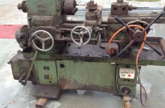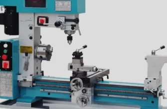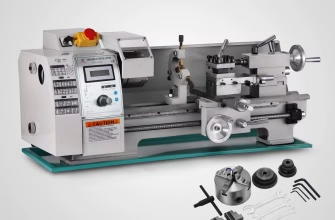
A capstan lathe is a semi-automatic precision lathe designed for high-volume production of small to medium components. Unlike turret lathes with fixed turrets, capstan lathes feature a sliding ram-mounted capstan turret that moves toward the work, dramatically reducing cycle time and operator fatigue. The 6-station indexing turret holds multiple cutting tools (drills, boring bars, dies, reamers) that perform sequential operations on bar stock in rapid succession. Capstan lathes remain essential in modern manufacturing for small-batch production of fasteners, connectors, and precision fittings – especially in shops where CNC investment isn’t justified.
1. Introduction
What This Guide Will Cover
This article provides a complete technical breakdown of how capstan lathes work, with emphasis on turret head mechanics, operation cycles, and practical setup guidance. You’ll learn the mechanical architecture that makes capstan lathes unique, understand the sequential tooling strategy, and discover why they remain competitive against CNC machines for specific production scenarios.
Why Capstan Lathes Remain Relevant in Modern Production
Despite CNC technology’s dominance, capstan lathes continue operating in thousands of shops worldwide. Here’s why: they require minimal operator skill, deliver predictable cycle times, need no computer programming, and cost a fraction of CNC equipment. For shops producing 100–5,000 units of the same part, capstan lathes deliver profitability that CNC systems cannot match. They’re also ideal for contract manufacturers, tool-and-die shops, and emerging markets where equipment investment must be conservative.
Where They Fit in the Lathe Family (Quick Overview)
The lathe family spans three main categories:
- Engine/Center Lathe: Manual operation, versatile, slow cycle times, requires skilled operator
- Turret Lathe: Fixed turret on carriage, faster than engine lathe, heavier duty
- Capstan Lathe: RAM-mounted turret, fastest cycle times, most compact, ideal for high-volume small parts
This article focuses exclusively on capstan lathes and their unique operating principles.
2. What Is a Capstan Lathe? (Clear Definition)
Core Purpose: Semi-Automatic, High-Volume Production Lathe
A capstan lathe is a production lathe designed to perform multiple cutting operations on bar stock automatically through sequential tool indexing. Unlike manual lathes, the capstan requires no skill – just load a bar, press a lever or foot pedal, and the machine completes the entire operation cycle. The “semi-automatic” designation means the operator controls cycle start/stop, but the machine executes all cutting sequences independently.
Capstan lathes can produce 50–200 finished parts per hour, depending on workpiece complexity. They’re engineered specifically for repeatability and speed, not versatility.
Difference Between: Capstan Lathe, Turret Lathe, and Engine Lathe
| Characteristic | Engine/Center Lathe | Turret Lathe | Capstan Lathe |
|---|---|---|---|
| Turret Type | None (single tool) | Fixed on carriage | Sliding ram-mounted |
| Automation | Manual | Semi-auto | Semi-auto |
| Cycle Time (per part) | 5–30 min | 1–5 min | 30 sec–2 min |
| Skill Required | High | Medium | Low |
| Part Size Range | 1″–12″+ diameter | 0.5″–4″ diameter | 0.125″–2″ diameter |
| Tool Capacity | 1–2 tools | 6–8 stations | 6 stations |
| Ideal Volume | Custom/prototype | 500–5,000 pcs | 1,000–50,000 pcs |
| Rigidity | Highest | High | Medium |
| Cost New | $40K–$150K | $80K–$300K | $50K–$200K |
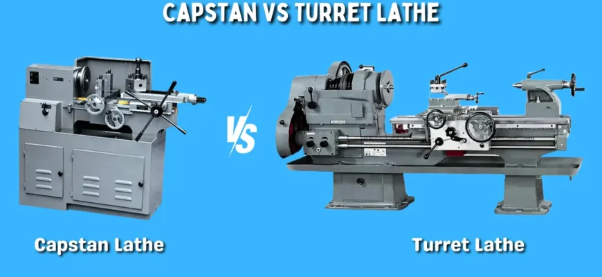
The key mechanical difference: turret lathes have a turret that rotates on a fixed carriage, while capstan lathes have a turret mounted on a sliding ram that moves toward the spindle. This design difference is the foundation of capstan speed.
Typical Industries and Workpiece Types
Capstan lathes dominate specific sectors:
- Fastener Industry: Screws, bolts, studs, rivets (billions produced annually)
- Automotive Suppliers: Ball joints, connector pins, fuel injector components
- Electrical: Terminal lugs, connector bodies, contacts
- Medical Devices: Small precision screws, implant components
- Plumbing/Hardware: Valve stems, faucet internals, hose fittings
- General Contract Manufacturing: Any small part requiring multiple operations
Typical workpiece characteristics:
- Diameter: 0.125″ to 2.0″ (3–50mm)
- Length: 0.5″ to 6″ (12–150mm)
- Material: Steel, stainless steel, aluminum, brass, plastics
- Volume: 500–100,000 identical pieces
3. The Capstan Lathe Architecture
3.1 Capstan vs Fixed Turret: Mechanical Design Difference
The defining feature of a capstan lathe is its sliding turret mounted on a powered ram.
Fixed Turret Lathe (Traditional):
- Turret bolts to the carriage saddle
- Carriage moves toward the headstock
- Tool-to-work distance changes as carriage advances
- Requires longer approach distance for each tool
Capstan Lathe (Ram-Mounted):
- Turret bolts to a sliding ram (horizontal hydraulic or mechanical device)
- Ram moves independently of carriage
- All turret stations approach work from the same reference point
- Dramatically reduces rapid-traverse time between tools
Why Capstan Design Increases Speed and Reduces Operator Fatigue
When a capstan turret positions tool #2, it doesn’t move the entire carriage – it just indexes the turret and advances the compact ram toward the spindle. This achieves three critical advantages:
- Shorter rapid-traverse distance: Ram travel (2–4″) vs. carriage travel (6–12″), cutting cycle time by 40–60%
- Consistent tool approach: All tools reference the same starting position, eliminating manual adjustment
- Reduced operator effort: Simple lever or foot-pedal activation instead of complex carriage control
For a shop running 10,000 screws per day, capstan design saves 2–3 hours of cycle time daily.
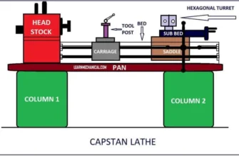
3.2 Major Components (Explained Simply + Technically)
Lathe Bed
The cast iron foundation that supports all moving assemblies. Capstan beds are shorter than turret lathes (typically 36–60″ long) and more compact. The bed contains two parallel ways (machined surfaces) that guide carriage and ram movement. Bed rigidity directly affects tool chatter – a worn bed creates vibration and poor surface finish.
Headstock
Houses the spindle and bearing assembly. The headstock is bolted to the left end of the bed and contains:
- Main spindle (hardened steel shaft rotating 200–3,000 RPM)
- Ball/roller bearings (pre-loaded for minimal runout)
- Speed change mechanism (belt/pulley or gearbox for 4–12 speeds)
- Collet or chuck for gripping bar stock
Modern capstans use precision spindle bearings (runout ±0.0005″) to ensure concentricity.
Spindle & Speed Controls
The spindle rotates the workpiece. Capstan spindle speeds typically range 200–3,000 RPM, with 6–10 selectable speeds via:
- Stepped pulley system (belt tensioner adjusts speed manually – most common on older machines)
- Gearbox (internal gears, easier speed changes)
- Variable drive (on newer capstans, allows gradual RPM adjustment)
Speed selection depends on workpiece diameter and material. Larger parts run slower; smaller parts and soft materials (aluminum, brass) run faster.
Collet/Chuck System
The spindle nose holds either a precision collet chuck or power chuck. Capstans almost exclusively use collet chucks because they’re:
- Faster to load/unload
- More concentric (better runout)
- Simpler to operate (just pull-back collet lever and insert bar)
A typical collet chuck range is 0.125″–0.5″ (capstan standard), though larger machines accept up to 1.5″.
Carriage & Saddle
The carriage is the horizontal assembly that slides along the bed’s ways. It carries the saddle (vertical component), which holds:
- Cross-slide assembly (moves tool perpendicular to spindle axis)
- Longitudinal feed rod connection
- Coolant delivery points
On capstan lathes, the carriage stays relatively stationary during cycles. Its primary role is positioning the ram and managing longitudinal feed for some operations.
Capstan Slide (Ram)
The heart of capstan design: a powered, sliding turret mounting block that moves independently of the carriage. The ram is typically:
- Hydraulic (modern machines) – fast, smooth, adjustable force
- Mechanical (older machines) – cam-driven, requires more setup adjustment
Ram travel is typically 2–6 inches, controlled by:
- Pneumatic or hydraulic cylinders (push ram forward during cutting, retract rapidly)
- Stop rod adjustments (define how far ram advances before tool engages work)
Stop rods are the critical setup element: they define cycle timing and tool depth.
Six-Station Turret Head
A rotating indexing turret with six tool-holding stations (some models offer 8 stations for complex parts). Turrets typically measure 4–6 inches in diameter and rotate through 60° increments (360° ÷ 6 stations). Each station holds a tool or tooling block via:
- Square hole (universal standard, 1″–1.5″ square)
- Wedge or key lock (prevents rotation during cutting)
Tooling Blocks and Tool Holders
Tool holders are precision-ground steel blocks that clamp specific tools and lock into turret stations via a dovetail or square-hole interface. Standard types include:
- Drill chucks (small drills up to 0.5″)
- Boring bar holders (for internal finishing)
- Tap holders (with floating collet to prevent breakage)
- Die head holders (self-opening threading dies)
- Parting tool holders (cutoff blades)
Quality holders maintain ±0.005″ accuracy and survive thousands of impact loadings during rapid indexing.
Stop Rods and Indexing Mechanism
Stop rods are critical adjustment elements that define:
- How far the ram advances before tool contacts work
- When the machine cycles to the next station
- Feed rate during each operation
Stop rods sit on the carriage and rest beneath the ram. As the ram advances, it compresses or contacts these rods, triggering either:
- Mechanical stop (collision limit)
- Hydraulic limit switch (electronic pressure cutoff)
Misaligned or worn stop rods cause tool crashes, surface defects, and broken tooling.
Feed Rod & Lead Screw (Capstan-Specific Function)
The feed rod transmits rotating spindle motion to drive longitudinal (Z-axis) movement. Unlike engine lathes, capstan feed is automatic and highly regulated. The lead screw is indexed through:
- Friction clutch (disengages when feed is not needed)
- Reversible cam (for threading operations)
Feed rate (inches per revolution) is fixed during setup. This ensures consistent chip evacuation and surface finish across all parts.
Optional Attachments Found on Capstan Lathes
Bar Feeding Attachment: Automatic collet chuck with pneumatic advance. Feeds fresh bar stock after part cutoff, reducing operator intervention for very high volumes.
Self-Opening Die Heads: Specialized chasing threading attachment that automatically disengages after one rotation, preventing thread damage and reducing cycle time by 30%.
Box Tools: Hardened tool blocks that perform multiple operations (facing, center drilling, drilling) in a single turret station – reducing tool changes.
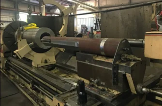
Roller Supports: Anti-vibration guides for long, thin bar stock (length-to-diameter ratio >15:1), preventing chatter and tool breakage.
4. The Turret Head: Heart of the Capstan Lathe
4.1 What Is a Turret Head?
The turret head is the rotating indexing assembly that holds up to six cutting tools and automatically rotates from one station to the next after each operation completes. Think of it as a revolver cylinder for industrial cutting – each station holds a different tool, and the turret “fires” tools in sequence.
6-Station Indexing Head Explained
Most capstan lathes have 6 stations arranged in a hexagon (60° spacing). The turret mounts to the sliding ram via a precision bearing ring and rotates through:
- Intermittent motion (snap rotation, not continuous)
- Positive indexing (stops precisely at each station via detent or pawl mechanism)
- Automatic or manual advance (triggered by cycle completion or operator button)
Each station can hold a simple cutting tool (drill, boring bar) or a complex tooling block (self-opening die, box turning tool).
Station Layout and Typical Tooling Arrangement
A standard 6-station arrangement might be:
| Station | Primary Tool | Secondary Tool | Purpose |
|---|---|---|---|
| 1 | Box facing tool | Center drill | Faces end, creates center point |
| 2 | Drill (main size) | – | Creates primary hole |
| 3 | Boring bar | – | Finishes hole to size |
| 4 | Threading die head | – | Adds thread (if needed) |
| 5 | Reamer or cutoff prep | – | Final sizing or thread cutoff |
| 6 | Cutoff/parting tool | – | Separates finished part |
Smart arrangement principles:
- Tools that create chips (drilling) come before finishing tools (reaming)
- Large-diameter tools position before small-diameter tools (prevents collisions)
- Cutoff tool always occupies the rearmost station (maximum clearance)
The sequence order directly impacts cycle time. A poor arrangement might require the ram to retract/advance multiple times; optimal sequences minimize total ram travel.
4.2 Turret Indexing Mechanism Explained
How Automatic Indexing Works Mechanically
After each tool operation completes, the machine must rotate the turret to the next station with precision and speed. Capstan indexing uses two primary methods:
Method 1: Pawl & Ratchet (Mechanical)
- A spring-loaded pawl (mechanical finger) engages a ratchet ring (gear-like component) beneath the turret
- As the turret rotates, the pawl advances across ratchet teeth
- A return spring snaps the turret to the next detent position
- Advantages: Rugged, no hydraulics required, simple adjustment
- Disadvantages: Audible “clunking,” wear over time, position can creep
Method 2: Geneva Mechanism or Hydraulic Detent (Modern)
- A hydraulic cylinder or solenoid triggers turret rotation
- Rotation stops automatically via mechanical detent (precision ball bearing in indexed groove)
- Advantages: Smooth, silent, precise, repeatable
- Disadvantages: Requires hydraulic system maintenance, higher initial cost
Most machines built after 1990 use hydraulic systems, while older capstans rely on mechanical pawl systems.
How Tool Alignment Is Ensured
Capstan turrets achieve precise alignment through:
- Precision Bearing Ring: The turret rotates on a hardened, preloaded bearing with runout typically ±0.0005″
- Turret Bottom Face Flatness: Machined to ±0.0003″ to seat flush against the ram
- Tool Holder Seating: Square-hole or dovetail interfaces machine to ±0.005″
- Spindle Runout Alignment: The spindle’s concentricity directly affects whether tools align with workpiece center
Alignment verification: A test dial indicator on the spindle nose should measure ±0.0003″ runout when turret rotates without tools. Any higher indicates:
- Worn spindle bearings
- Bent spindle nose
- Turret bearing play
- Incorrect tool height
Common Sources of Misalignment
Problem 1: Incorrect Tool Height
- Tools must sit at exact spindle centerline (Z-height)
- Tooling blocks too high or low cause cutting tool to miss workpiece center
- Result: chatter, poor surface finish, unexpected tool breakage
- Fix: Use precision height-setting gauge blocks and adjust tooling block shims
Problem 2: Stop Rod Wear
- Stop rods control ram advance distance
- Worn rods allow ram over-travel
- Tools crash into workpiece or spindle chuck
- Fix: Replace stop rods or adjust mechanical backstop position
Problem 3: Turret Backlash
- Mechanical pawl systems wear, allowing turret to slip between stations
- Hydraulic systems can lose pressure, preventing full turret advance
- Result: tool stations misaligned, creating chatter and crash risk
- Fix: Retension pawl spring, inspect hydraulic pressure, replace turret bearing if worn
Problem 4: Spindle/Chuck Runout
- A concentrically-mounted workpiece is essential
- Runout >0.001″ causes radial tool misalignment
- Fix: Clean spindle nose, verify collet jaw condition, use precision collet chuck
4.3 Types of Tools Mounted on a Turret
Box Turning Tool
A hardened steel block housing a carbide or HSS cutting tool, typically used for facing operations. Performs:
- Faces the end of bar stock square and flat
- Often integrates a center drill for locating secondary operations
- Usually occupies Station 1 (first operation after loading)
- Typical cycle time: 2–5 seconds
Drills & Counterbores
Jobber-length or stub drills mounted in precision chucks or collets. Typical sizes: 0.060″ to 0.5″ diameter. Capstans run drills at high spindle speeds (1,200–2,500 RPM) with automatic feed:
- Creates primary holes rapidly
- Counterbores enlarge holes or create spotface recesses
- Multiple drill stations allow cascading hole sizes (small → medium → large)
Boring Bars
Precision carbide-tipped bars for finishing internal holes to tight tolerances (±0.0005″). Boring bars:
- Follow rough drilling operations
- Produce superior surface finish and dimensional accuracy
- Allow adjustable cutting diameter for fine tolerance work
- Operate at moderate speeds (500–800 RPM) with light feed
Self-Opening Die Heads
Specialized threading attachments with segmented dies that automatically open after one spindle revolution, preventing thread overcut and damage. Die heads:
- Run at fixed speeds matched to thread pitch (typically 100–400 RPM)
- Auto-disengage after thread completion
- Dramatically faster than manual threading
- Critical for high-volume fastener production
Reamers & Tapping Tools
Precision reamers finish drilled holes to exact size (±0.0002″). Tapping tools hold spiral flute taps for creating internal threads. Both tools:
- Operate after drilling/boring to establish size
- Run at slow speeds with precise feed (matching thread pitch for taps)
- Require rigid support (collet or floating chuck) to prevent breakage
- Taps especially need anti-breakage design to handle interrupted cuts
Cutoff/Parting Tool
A hard-edged blade (carbide or HSS) that severs the finished part from bar stock. Parting tools:
- Usually mount in the rearmost turret station for maximum clearance
- Generate significant side load (requires rigid tooling)
- Critical for automatic operation – a broken parting tool stops the entire production run
- Typical width: 0.125″–0.25″
5. How a Capstan Lathe Works: Step-by-Step Operation
5.1 The Core Working Principle
A capstan lathe operates on repetitive automation: once setup is complete, the operator performs only two actions per cycle:
- Load: Insert bar stock into collet chuck (3 seconds)
- Start: Press foot pedal or cycle-start button (machine runs 30 seconds–2 minutes automatically)
- Unload: Remove finished part and repeat
The machine executes multiple cutting operations in sequence, with the sliding ram turret automatically advancing and retracting between operations.
Ram Movement vs Saddle Movement
Capstan operation involves two independent axis systems:
RAM MOVEMENT (Z-Axis Primary Control):
- The sliding turret ram moves toward the spindle (advance) and away (retract)
- Ram movement is rapid and precise (0.5–2 seconds per advance)
- Controlled by stop rods that define advance distance
- All tool stations use the same approach distance, eliminating tool-by-tool adjustment
SADDLE/CARRIAGE MOVEMENT (Z-Axis Secondary):
- The carriage saddle moves along the bed for threading operations or long-reach drilling
- Saddle movement is slower than ram movement (controlled by automatic feed rod)
- Typically used for only 1–2 operations in a cycle
- Most cycles use primarily ram movement for speed
Why This Matters: Ram design allows capstan lathes to complete 6-operation cycles in 30–60 seconds, while older turret lathes need 2–4 minutes for the same sequence.
5.2 Full Operation Cycle (Explained in Workflow Order)
Below is a complete real-world cycle for producing a precision fastener (screw) with 3/8″-16 UNC threads on a typical capstan lathe:
STEP 1: OPERATOR LOADS BAR STOCK
- Pull collet sleeve lever backward (opens collet jaws)
- Insert 0.375″ steel bar into collet
- Release lever (collet closes, grips bar tightly)
- Bar should protrude exactly 1.25″ (length-stop distance)
- Cycle time: 3–4 seconds
STEP 2: OPERATOR PRESSES CYCLE-START BUTTON
All subsequent operations are fully automatic.
STEP 3: SPINDLE STARTS, TURRET POSITION #1 (FACING)
- Spindle accelerates to 800 RPM
- Turret auto-indexes to Station 1 (if not already there)
- Facing tool advances via ram (0.15″ travel)
- Tool faces the end of bar stock perpendicular and flat
- Rapid retraction when tool contacts stop rod
- Cycle time: 3–4 seconds | Coolant: Heavy stream on tool
STEP 4: TURRET AUTO-INDEX TO POSITION #2 (CENTER DRILL)
- Spindle maintains 800 RPM
- Turret rotates 60° to next station (instantly)
- Center drill (0.125″ diameter) advances via ram
- Drill creates small conical indentation at bar center for locating subsequent drills
- Prevents drill wandering during main drilling operation
- Cycle time: 2 seconds | Coolant: Medium flow
STEP 5: TURRET AUTO-INDEX TO POSITION #3 (MAIN DRILL)
- Spindle speed increases to 1,500 RPM (automatic via mechanical linkage or manual pre-selection)
- Turret indexes to Station 3 (main drill: 0.281″ diameter for 3/8″-16 thread clearance hole)
- Automatic feed rod engages, rotating spindle motion into Z-axis drill advance
- Drill penetrates 0.8″ depth (as determined by stop rod position)
- Breakthrough: Coolant flushes chips from hole
- Stop rod triggers rapid retraction
- Cycle time: 8–12 seconds | Coolant: Heavy flood cooling
STEP 6: TURRET AUTO-INDEX TO POSITION #4 (BORING/REAMING)
- Spindle speed reduced to 600 RPM (for precision finishing)
- Turret indexes to Station 4 (carbide boring bar)
- Ram advances 0.75″
- Boring bar rotates at precise speed, automatic light feed (0.003″ per revolution)
- Finishes hole to exact 0.281″ diameter ± 0.0003″
- Boring bar retracts
- Cycle time: 6–8 seconds | Coolant: Light flow (prevents thermal distortion)
STEP 7: TURRET AUTO-INDEX TO POSITION #5 (THREADING)
- Spindle speed fixed at 100 RPM (determined by thread pitch: 3/8″-16 UNC = 100 RPM for optimal speed)
- Turret indexes to Station 5 (self-opening die head)
- Die head advances via ram 0.5″
- Die head threads 1.0″ of 3/8″-16 UNC thread (as per specification)
- After one complete spindle revolution, dies automatically open (no over-thread)
- Ram retracts rapidly
- Cycle time: 6–8 seconds | Coolant: Medium-heavy flow (thread quality critical)
STEP 8: TURRET AUTO-INDEX TO POSITION #6 (PARTING OFF)
- Spindle speed returns to 300 RPM (lower for cutting force control)
- Turret indexes to Station 6 (parting tool, rearmost position)
- Parting tool (0.125″ blade) advances via ram 0.10″ per pass (multiple passes, not single cut)
- Each pass cuts deeper until finished part severs from bar stock
- Finished screw drops into collection bin below spindle
- Bar stock is now ready for next cycle
- Ram fully retracts
- Cycle time: 8–10 seconds | Coolant: Heavy flood (prevents tool breakage)
STEP 9: AUTO-INDEX RETURNS TURRET TO POSITION #1
- Machine cycles back to start position
- Spindle maintains light rotation
- Ready for next bar stock load
TOTAL CYCLE TIME: 45–55 seconds per part
If running 10-hour shift: 650–800 finished parts per day
5.3 Feed Systems
Hand Feed vs Automatic Feed
Automatic Feed (Most Common):
- Lead screw engaged via friction clutch to spindle rotation
- Cutting feed advances proportional to spindle RPM
- Feed rate is fixed in inches-per-revolution (typically 0.003″–0.015″)
- Machine maintains consistent chip load regardless of spindle speed
- Advantage: No operator adjustment needed; highly repeatable surface finish
Hand Feed:
- Operator manually controls feed via hand-wheel
- Used only for non-standard operations or troubleshooting
- Slower and requires skill
- Rarely used on production capstans – only on older machines
Rapid Indexing
Between cutting operations, the machine must rapidly retract and advance the ram without cutting:
- Rapid advance: Pressurized hydraulic or compressed air pushes ram toward spindle quickly (typically 20–40″ per second)
- Rapid retract: Spring or reverse hydraulic pressure pulls ram back (even faster, 40–60″ per second)
- Smooth transitions: No jerking or vibration (tight tolerance guideways required)
Rapid indexing is critical to cycle time – if rapid traverse speed drops by 50%, cycle time increases by 20–30%.
Return Strokes
After each cutting operation:
- Tool completes cut (as determined by stop rod engagement)
- Feed disengages (friction clutch releases)
- Ram retracts rapidly via hydraulic pressure
- Turret rotates (while ram is retracting)
- Ram returns to “ready” position before next advance
A smooth return stroke prevents tool crashes and ensures turret alignment precision.
Why Cycle Time Becomes Extremely Consistent
Once setup is complete, every single part’s cycle time is virtually identical (±1–2%). This consistency is unprecedented in manual machining and rivals CNC for predictability. Reasons:
- Automatic feed removes operator variable
- Fixed stop rods define exact tool advance distance (no guessing)
- Rapid indexing speed is mechanical (spindle-based), not operator-dependent
- Tool engagement and disengagement is automatic (no hand-wheel adjustment)
This cycle-time consistency enables accurate production scheduling and inventory planning – essential for contract manufacturers meeting customer deadlines.
6. Capstan Lathe Operations (Complete List)
Capstan lathes can perform virtually all chip-removing operations suitable for small bar stock. Here’s the complete operational repertoire:
Facing
Removes end material to create a flat, perpendicular surface. Box facing tools are specialized for rapid facing (2–4 seconds per face).
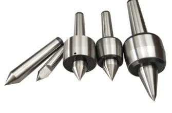
Center Drilling
Creates small conical indentation using a combined center drill, locating subsequent drills and preventing walk-off.
Drilling
Primary hole creation using jobber-length or stub drills up to 0.5″ diameter. Multiple drill stations allow cascading hole sizes.
Boring
Precision hole finishing using carbide boring bars to ±0.0005″ concentricity. Often follows rough drilling.
Reaming
Precision hole sizing and surface finish improvement using spiral-flute or straight reamers.
Tapping/Threading
Internal thread creation using either:
- Tapping tools (spiral-flute taps for thread cuts)
- Self-opening die heads (external thread creation via chasing)
Knurling
Rolling serrated or diamond patterns onto cylindrical surfaces for grip enhancement. Specialized knurling tools generate patterns at spindle speed.
Grooving
Creating circumferential grooves or undercut recesses using hardened groove tools.
Parting
Separating finished part from bar stock using precision parting blades.
Multiple Operations in Single Sequence
The unique capstan advantage: combining 4–8 different operations in a single 30–120-second cycle, delivering finished assemblies instead of rough castings.
7. Capstan vs Turret Lathe: True Differences (Deep Explanation)
While capstan and turret lathes may appear similar, their mechanical differences create significant operational divergence:
Turret Mounting Difference
Turret Lathe:
- Turret bolts directly to carriage saddle
- Carriage (with turret attached) moves toward spindle
- Tool approach distance varies if carriage position isn’t reset between operations
Capstan Lathe:
- Turret bolts to independent sliding ram
- Ram moves toward spindle (carriage stays relatively stationary)
- All tools approach from consistent reference point
Implication: Capstan design reduces setup complexity and eliminates tool-by-tool carriage positioning.
Production Volume Suitability
| Volume | Best Machine | Reason |
|---|---|---|
| 100–500 pcs | Engine Lathe | Setup time amortized across small volume; turret setup overkill |
| 500–5,000 pcs | Turret Lathe | Justified setup time; heavier duty; more forgiving of slightly variable tool engagement |
| 5,000–50,000 pcs | Capstan Lathe | Rapid cycle time justifies dedicated setup; ram efficiency maximizes throughput |
| 50,000+ pcs | CNC or Capstan | CNC if tolerance demands ultra-tight; capstan if tolerances acceptable and volume justifies |
Size & Rigidity
Turret Lathe:
- Larger, heavier machine (typical: 1,500–3,000 lbs)
- More rigid bed (accepts heavier cuts)
- Larger swing (workpiece diameter up to 4″–6″)
Capstan Lathe:
- Compact, lighter (typical: 800–1,500 lbs)
- Less rigid (smaller cross-section bed and ways)
- Smaller swing (workpiece diameter typically 0.125″–2.0″)
Why: Capstan design prioritizes speed over power. Small-diameter parts don’t require heavy cutting forces, so reduced rigidity is acceptable trade-off.
Workpiece Diameters
| Machine Type | Typical Workpiece Diameter | Collet/Chuck Size |
|---|---|---|
| Turret Lathe | 0.5″–4.0″ | 0.375″–1.5″ |
| Capstan Lathe | 0.125″–2.0″ | 0.125″–0.5″ |
| Engine Lathe | 1″–12″+ | 1″–4″+ |
Capstan collets are precision-engineered for small diameter bar stock, achieving better TIR (Total Indicated Runout) than larger turret chucks.
Cycle Time Comparison
Assuming identical 6-operation sequence on a 0.375″ diameter steel fastener:
| Operation Sequence | Engine Lathe | Turret Lathe | Capstan Lathe |
|---|---|---|---|
| 1. Face (3 sec) | 30 sec | 5 sec | 3 sec |
| 2. Center drill (2 sec) | 30 sec | 4 sec | 2 sec |
| 3. Drill (10 sec) | 60 sec | 12 sec | 8 sec |
| 4. Bore (8 sec) | 45 sec | 10 sec | 6 sec |
| 5. Thread (8 sec) | 45 sec | 10 sec | 7 sec |
| 6. Parting (10 sec) | 60 sec | 12 sec | 8 sec |
| TOTAL CYCLE TIME | 270 seconds | 53 seconds | 34 seconds |
| Parts/Hour | 13 | 68 | 106 |
Capstan cycle time is 40% faster than turret lathe for this sequence.
Tool Capacity
| Machine | Standard Stations | Extended Capacity |
|---|---|---|
| Turret Lathe | 6–8 stations | Up to 12 (8 on turret + 4 on rear tool post) |
| Capstan Lathe | 6 stations | 8 stations (special order) |
Capstan limitation is mechanical: larger turrets create imbalance and complicate rapid indexing.
Skill Level Required
Engine Lathe: Skilled operator (apprenticeship-level training required)
- Must understand cutting speeds, feeds, tool geometry
- Manual control of multiple axes simultaneously
- Interprets blueprints, makes adjustments mid-cycle
Turret Lathe: Semi-skilled operator (weeks to months training)
- Understands basic tooling and stop-rod adjustment
- Recognizes when setup is incorrect
Capstan Lathe: Unskilled operator (days to weeks training)
- Load bar, press button, unload part
- Minimal troubleshooting required
- Primarily monitors for tool breakage or chatter warnings
8. Advantages of Capstan Lathes
Standardized Operations
Every part produced is identical to the previous one. Standardization means:
- Predictable quality (no operator-induced variation)
- Simplified inspection (sample-test instead of 100% QA)
- Consistent scrap rates and tool life
- Easier documentation for regulatory compliance (aerospace, medical devices)
Extremely Fast Cycle Times
30–120 seconds per complete operation, compared to:
- Engine lathe: 300+ seconds
- Turret lathe: 60–180 seconds
- CNC mill: 120–300 seconds (if program is optimized)
Fast cycle times deliver:
- Rapid ROI (tooling investment recovered quickly)
- High daily output (500–2,000 parts/shift possible)
- Reduced per-unit manufacturing cost
Lower Operator Skill Needed
Operator training time: 1–2 weeks vs. 1–2 years for engine lathe. Benefits:
- Reduced training investment
- Easier to find replacement operators
- Lower wages (semi-skilled vs. machinist wages)
- Consistent performance (no operator drift)
Compact vs Turret Lathes
Capstan lathes occupy 50–70% of floor space compared to turret lathes. Advantages:
- Fits into smaller job shops
- Lower facility rent allocation per machine
- Multiple capstans fit where single turret lathe sits
Ideal for Small to Medium Batch Production
Capstan efficiency zone: 1,000–50,000 identical parts. At this volume:
- Setup time (2–4 hours) is justified
- CNC investment (often $150K–$500K) is overkill
- Manual production is insufficient
8.1 Limitations
Lower Rigidity vs Turret Lathe
Capstan beds are lighter, waviness under heavy cutting reduces:
- Surface finish quality (chatter marks visible)
- Tool life (vibration accelerates wear)
- Achievable tolerances (drift toward ±0.005″ instead of ±0.001″)
Mitigation: Use carbide inserts (less chatter-prone than HSS), reduce feed rates, check bed geometry with precision straightedge.
Not Suitable for Heavy Cuts
Capstan design prioritizes speed over power. Heavy-duty operations (large-diameter boring, heavy facing) cause:
- Tool chatter and breakage
- Spindle bearing overload
- Poor surface finish
When to use turret lathe instead: Large-diameter parts, interrupted cuts, or precision aerospace components requiring maximum rigidity.
Limited Bar Size
Standard capstan collets accept 0.125″–0.5″ diameter bar (larger machines up to 1.0″). Exceeding this:
- Requires larger machine (which reduces speed advantage)
- Turns application over to turret or engine lathe
9. Modern Applications & Industries Using Capstan Lathes
Despite CNC dominance, capstan lathes thrive in specific niches where their speed-to-cost advantage remains unmatched.
Hardware Manufacturing
Producing bolts, screws, nuts, rivets in massive volumes (millions annually). Example products:
- 1/4″-20 socket head cap screws (10M+ units/year)
- Stainless steel fasteners for construction
- Specialty fasteners for automotive assembly plants
Why capstan: CNC costs $2–3 per unit to produce; capstan costs $0.15–$0.30. At 5M units/year, capstan saves $10M+ in production costs.
Auto Parts and Fittings
Brake system components, fuel injector bodies, ball joint stems, transmission shafts. Example:
- Fuel injector pintle (300K+ units annually, 1/4″ diameter, multiple operations)
- Brake line fittings (5M+ units/year)
- Transmission clutch hub components
Why capstan: Complex multi-operation sequences (5–8 stations) fit perfectly; cycle times 45–90 seconds deliver daily volumes no manual lathe can match.
Electrical Connectors
Precision terminal lugs, contact pins, connector bodies. Example:
- Tin-plated copper terminals for automotive wiring (50M+ units/year)
- Precision connectors for aircraft avionics
- Digital device charging contacts (refined from 0.020″ sheet stock)
Why capstan: Tiny workpieces (0.125″–0.375″ diameter), high precision (±0.001″), extreme volumes justify dedicated capstan lines.
Precision Small Components
Aerospace fasteners, medical device screws, instrumentation bodies. Example:
- Surgical screw for orthopaedic implants (±0.0005″ tolerance, 10K+ units/year)
- Aircraft-grade fasteners (AS25042 specifications, titanium material)
- Sensor housing bodies (stainless steel, intricate threading)
Why capstan: Setup time justified for medical/aerospace volumes; superior surface finish vs manual; ultra-low scrap rates meet quality demands.
Fastener Industry
The historic and ongoing stronghold of capstan lathes. Products:
- Socket head cap screws (every diameter/length combination, 1B+ units globally/year)
- Machine screws, wood screws, sheet metal screws
- Specialty fasteners (captive fasteners, breakaway fasteners, security screws)
Modern fastener shops operate 100–500 capstan lathes simultaneously, feeding millions of fasteners monthly to distributors and OEMs.
High-Volume Workshop Production
Contract manufacturers and job shops producing diverse fasteners/components under varying customer specs. Example scenario:
- Monday: 5K stainless steel 3/8″-16 x 2″ socket head caps
- Tuesday: 3K brass 6-32 set screws
- Wednesday: 2K steel eyebolts with 1/4″-20 thread
A versatile capstan accommodates quick changeovers (30 minutes per job) at speeds CNC cannot match for this production model.
10. Capstan Lathe Setup: Practical Guide
10.1 Setting Up Tools on the Turret
Step 1: Choosing Correct Sequence
Before touching a tool, plan the operation sequence on paper:
- Identify all operations needed (facing, drilling, boring, threading, parting)
- Sequence by logical progression: Rough → finish, small → large diameter
- Minimize ram travel: Place geographically compatible tools adjacent on turret
- Avoid tool collisions: Ensure tools don’t interfere when adjacent stations are accessed
Example sequence for a fastener:
- Station 1: Facing (square the end)
- Station 2: Center drill (locate subsequent drills)
- Station 3: Main drill (primary hole)
- Station 4: Boring bar (finish hole)
- Station 5: Threading die head (add thread)
- Station 6: Parting tool (cut off)
This sequence ensures logical progression and maximum tool clearance.
Step 2: Setting Length Stops
Length stops define how far the ram advances before contacting the workpiece. Incorrect stops cause crashes or incomplete operations.
Procedure:
- Load sample workpiece in spindle collet (use actual production part or precisely-made test bar)
- Manually index turret to Station 1 (facing tool)
- Set spindle to operating speed (e.g., 800 RPM for facing)
- Manually advance ram using hand-lever or jog-button until facing tool just touches workpiece end (listen for light contact sound)
- Lock ram position via hydraulic or mechanical stop
- Adjust stop rod beneath ram to contact stop cylinder or pressure relief at this exact position
- Mark position with paint or tape for reference
- Repeat for each turret station, adjusting stops individually
Common Stop Rod Setup Error: Operators set stops too deep (ram over-travels), causing tool to crash into workpiece or spindle chuck. Always leave 0.050″–0.100″ clearance for safety.
Step 3: Aligning Tools
Tool alignment verification:
- Mount test indicator on spindle nose (dial indicator pointing at workpiece centerline)
- Index turret to each station individually
- Observe indicator runout as turret rotates (should be ±0.001″ or better)
- If runout exceeds ±0.003″, investigate:
- Spindle runout (use test bar in spindle, rotate spindle alone)
- Turret bearing wear (spin turret manually, listen for grinding)
- Tool holder seating (remove tool, clean dovetail, reinstall)
Step 4: Adjusting Center Height
All tools must sit at spindle centerline (Z-height). Incorrect height causes:
- Tool misses workpiece (too high)
- Tool digs in and breaks (too low)
Adjustment:
- Use precision height gauge blocks (stacked to spindle centerline height)
- Place gauge blocks in workpiece location (where bar stock sits)
- Position each tool so cutting edge just touches top of gauge blocks
- Lock tool height via tooling block shims (steel plates under tool base)
- Verify height by advancing tool lightly and confirming even contact across cutting edge
Pro tip: Mark correct height on machine bed with permanent marker (reference for future setups of similar parts).
Step 5: Test Run
Always perform single-cycle dry run before full production:
- Load test bar stock (same material as production parts)
- Run machine through full cycle (no spinning spindle initially, just ram advance/retract)
- Observe ram travel, tool indexing, and stop rod engagement
- Verify tool engagement sequence (does Station 1 tool engage workpiece correctly?)
- Run cycle with spindle engaged at reduced speeds (500 RPM instead of 1,500)
- Produce 3–5 test parts and inspect dimensions and surface finish
- Adjust feeds/speeds if needed, then begin full production
10.2 Common Setup Errors
ERROR #1: Misaligned Stop Rods
Symptom: Tool crashes into workpiece or spindle chuck on certain operations.
Cause: Stop rods weren’t set for specific tool station, or hydraulic pressure setting is incorrect.
Fix:
- Manually advance ram to each tool position and verify contact with stop rod
- Re-adjust stop rod or hydraulic limit pressure
- Test with low spindle speed before production
ERROR #2: Wrong Tool Sequence
Symptom: Produced parts are incomplete or incorrect (missing operations, wrong thread pitch, etc.).
Cause: Tools weren’t sequenced logically; operator misunderstood production drawing.
Fix:
- Review drawing and re-plan sequence from scratch
- Re-index turret and verify each tool is correct for intended operation
- Produce test parts and measure all dimensions
ERROR #3: Excessive Tool Overhang
Symptom: Tool chatter, poor surface finish, tool breakage.
Cause: Cutting tool extends too far from tooling block; cantilever creates deflection under cutting force.
Fix:
- Minimize tool overhang (general rule: overhang < 2× tool diameter)
- Use carbide tools (more rigid than HSS for small overhang)
- Reduce feed rate or spindle speed if chatter persists
ERROR #4: Incorrect Feed Rates
Symptom: Chips too large (tool breakage), chips too small (poor cooling), surface finish inadequate.
Cause: Feed lever set to wrong position or automatic feed rate miscalculated.
Fix:
- Typical feed rates: 0.003″–0.015″ per revolution (varies by material)
- Adjust friction clutch on feed rod to achieve desired feed
- Produce test parts and inspect chip color/curl (golden = optimal, black = too much feed)
11. Maintenance, Wear Points & Longevity Tips
Daily Lubrication Points
A well-maintained capstan lathe can operate 20+ years. Daily maintenance (10–15 minutes) includes:
| Component | Lubricant Type | Frequency | How To |
|---|---|---|---|
| Bed ways | Machine oil (ISO 32) | Daily | Wipe old oil away; apply thin coat with soft cloth |
| Carriage saddle | Machine oil (ISO 32) | Daily | Oil lubrication channels along carriage underside |
| Ram slide | Machine oil (ISO 32) | Daily | Oil exposed ram slideways before/after production |
| Turret bearing | Grease (NLGI 2) | Weekly | Apply grease fitting if equipped; rotate turret |
| Spindle bearing | Machine oil or automatic system | Daily | Check oil level in headstock reservoir; top up if needed |
| Feed rod/screw | Machine oil (ISO 32) | 2x weekly | Oil along feed rod length to prevent corrosion |
| Hydraulic system | Hydraulic fluid (AW 32) | Monthly | Check fluid level; top up if below minimum |
Critical: Proper lubrication doubles machine service life and prevents costly spindle bearing replacement ($3K–$8K).
Turret Indexing Care
The turret indexing mechanism is highest-wear component. Prevention:
- Keep turret rotating smoothly: Daily rotation (no load) ensures pawl/detent stays free
- Listen for grinding sounds: Metallic grinding indicates bearing wear; inspect immediately
- Monitor indexing precision: Dial indicator check monthly – if runout exceeds ±0.003″, bearing needs replacement
- Prevent debris: Cover turret when not running; dirt/metal chips accelerate wear
Ram Slide Cleaning
Ram slides (Z-axis guideways) accumulate chips and coolant sludge, reducing smooth travel:
- Daily wipedown: Use lint-free cloth; wipe chips from exposed slideways
- Weekly deep clean: Use soft brush and compressed air; blow out accumulated debris
- Monthly: Apply light machine oil after cleaning
- Signs of trouble: Rough ram motion, jerky indexing, unusual noise during traverse
Headstock Bearing Inspection
Spindle bearings are critical to accuracy and tool life. Inspection schedule:
| Inspection Type | Frequency | How To |
|---|---|---|
| Visual/Sound | Daily | Listen for grinding or clicking; observe for leakage |
| Runout check | Monthly | Mount test indicator; spindle should runout < 0.0005″ |
| Temperature | Weekly | Touch headstock housing (should be warm, not hot) |
| Axial play | Quarterly | Grip spindle nose; check for end-play (should be zero) |
Warning signs requiring bearing replacement:
- Runout exceeds ±0.001″
- Grinding noise from headstock
- Spindle temperature excessive (>60°C / 140°F)
- Visible oil leakage from headstock seals
Coolant Maintenance
Capstan lathes consume high-volume coolant (10–40 gallons/shift). Neglected coolant causes:
- Tool life reduction (30–50%)
- Surface finish degradation
- Spindle bearing rust
- Operator health issues (skin irritation, respiratory)
Maintenance schedule:
- Daily: Check coolant level; top up if below minimum sight glass
- Weekly: Skim surface debris and tramp oils using coolant skimmer
- Monthly: Test coolant pH (should be 8.5–10.0); add biocide if bacterial growth detected
- Quarterly: Full coolant change (drain system, flush lines, refill with fresh coolant)
Modern coolant systems include automatic concentration control and bacterial monitoring – systems reduce maintenance burden.
How to Detect Turret Misalignment Early
Misalignment begins subtly and worsens over months. Early detection prevents crashes and scrap:
Test 1: Dial Indicator Runout (Monthly)
- Mount dial indicator on spindle nose
- Rotate empty turret slowly (no tools)
- Observe indicator needle – should not exceed ±0.001″
- If 0.001″–0.003″: bearing developing play; monitor closely
- If >0.003″: bearing requires replacement within weeks
Test 2: Tool Engagement Consistency
- Produce 5 test parts across different turret stations
- Measure critical dimensions (hole diameter, thread pitch)
- If dimensions vary ±0.005″ between stations: misalignment likely
- If variation pattern matches turret station: bearing wear confirmed
Test 3: Audible/Tactile Feedback
- Index turret manually while listening closely
- Smooth rotation: bearing healthy
- Grinding, clicking, or rough spots: bearing needs service
- Sluggish rotation: debris in bearing race; clean immediately
12. Capstan Lathes in Modern Manufacturing (2025 Perspective)
CNC Conversions
Vintage capstan lathes (many dating to 1960s–1990s) are experiencing second lives via CNC retrofits. Shops invest $30K–$60K to retrofit mechanical capstans with:
- Servo motors (spindle speed control)
- Stepper motors (turret indexing)
- PLC controller (cycle automation)
- Digital readouts (DRO) (dimensional feedback)
Advantage: Combines capstan speed advantage with CNC precision and flexibility. Retrofitted capstans produce ±0.001″ tolerances with 45-second cycle times.
Digital Readouts (DRO)
Modern capstans often integrate digital display systems showing:
- Real-time spindle RPM
- Cycle time counter
- Parts produced count (auto-incrementing)
- Feed rate in/sec (real-time monitoring)
DROs improve operational visibility but don’t fundamentally change capstan operation – they’re data capture tools, not automation upgrades.
Hybrid Semi-Automatic Systems
Emerging “hybrid capstans” combine capstan speed with CNC flexibility:
- Automatic tool changers (8–12 tools instead of 6-station turret)
- Programmable cycle sequencing (operator selects program vs. fixed hardwired sequence)
- Precision boring headstocks (for ±0.0005″ internal tolerances)
- Multi-spindle capability (simultaneous operation on multiple bar stocks)
These hybrid systems cost $150K–$300K (vs. traditional capstan $50K–$80K) but rival older CNC machines in flexibility while maintaining capstan speed advantage.
Why Small Shops Still Rely on Them
Despite CNC’s capabilities, capstan lathes dominate small shop production for specific reasons:
- Capital efficiency: $50K capstan vs. $250K CNC; ROI timeline dramatically shorter
- Programming complexity eliminated: No CAM software, G-code debugging, tool path generation – just load tools and press button
- Flexibility within batch: Change bar diameter from 0.375″ to 0.25″? Adjust collet and stop rods (15 minutes vs. 2 hours CAM programming)
- Operator skill mismatch: Small shops can’t afford full-time CNC programmers; capstan operators are ubiquitous
- Rapid market response: Quote received Monday, first 100 parts delivered Wednesday (CNC would need 2 days programming alone)
Real scenario: A fastener distributor receives urgent order for 5,000 pieces of obscure fastener. Capstan shop can set up and ship within 36 hours; CNC shop needs 5+ days for programming and setup.
13. Frequently Asked Questions
Q1: How does a capstan lathe differ from a turret lathe?
A: The fundamental difference is turret mounting:
- Capstan: Turret bolts to a sliding ram that moves independently toward the spindle
- Turret: Turret bolts to the carriage saddle that moves along the bed
This design difference creates 40% faster cycle times for capstan (ram travel is shorter and more direct than carriage travel). Capstans are optimized for very high-volume small parts (5K–50K units); turret lathes are better for larger workpieces and heavier cuts.
Q2: What is a turret head used for?
A: The turret head holds multiple cutting tools in indexed stations (typically 6 stations), enabling automatic sequential tool changing without operator intervention. Instead of manually changing tools between operations, the turret automatically rotates to the next tool station after each cutting pass completes. This automation is the primary productivity advantage over manual lathes.
Q3: What operations can be done on a capstan lathe?
A: Capstan lathes can perform any chip-removing operation suitable for small bar stock:
- Facing, center drilling, drilling, boring, reaming
- Tapping, threading (via self-opening dies)
- Knurling, grooving, parting
- Combinations of the above in single automated cycles
The machine cannot perform: complex contours (require multi-axis CNC), interrupted cuts (excessive vibration), or extremely large workpieces (diameter >2″).
Q4: Why is the ram design important?
A: The sliding ram eliminates carriage re-positioning between tool stations. Each tool approach is consistent and rapid – typically 2–4 seconds vs. 6–12 seconds for turret lathe carriage travel. This design advantage scales dramatically with high-volume production: on a 5,000-piece run, ram efficiency saves 8–16 hours of machine time. The ram design is the core advantage enabling capstan’s speed.
Q5: Can capstan lathes be replaced by CNC machines?
A: Partially yes, but economically questionable for high-volume small parts:
- CNC Advantages: Flexibility (program any geometry), precision (±0.0001″), repeatability
- Capstan Advantages: Speed (2–5× faster for simple parts), simplicity (no programming), lower cost ($50K vs. $250K)
Decision framework:
- Volume <1,000 pcs: CNC is overkill; manual lathe or capstan
- Volume 1K–50K pcs, simple geometry: Capstan wins on cost/time
- Volume 5K–100K pcs, complex geometry: CNC or hybrid capstan wins
- Volume >100K pcs: Dedicated high-volume CNC or capstan production line
For the fastener industry, billions of parts annually are still produced on capstan lathes because CNC simply cannot match their speed-to-cost ratio for high-volume simple parts.
14. Conclusion
Summary of How the Machine Works
A capstan lathe is a semi-automatic production machine designed to manufacture small-diameter bar stock components at extremely high speeds through sequential multi-tool automation. The machine’s defining feature – a sliding ram-mounted turret – enables each cutting tool to approach the workpiece from a consistent reference point, dramatically reducing cycle time compared to turret lathes.
The operation cycle is fundamentally simple: load bar stock → press button → machine executes 4–8 cutting operations automatically → operator unloads finished part. This simplicity, combined with 40–60 second cycle times, delivers 500–2,000 finished parts per shift – production volumes incomparable with manual machining.
The turret head (typically 6 indexed stations) is the machine’s automation core, holding diverse tools (drills, boring bars, threading dies, parting tools) that rotate sequentially as each operation completes. Stop rods and hydraulic systems control exact tool engagement depth and rapid indexing speed, ensuring cycle-time consistency that rivals CNC machines.
When to Choose Capstan vs Turret or CNC Lathe
| Production Scenario | Recommended Machine | Reason |
|---|---|---|
| Single prototype or custom part | Engine lathe | Versatility and operator skill needed |
| 500–2,000 identical small parts | Capstan lathe | Setup time justified; fastest cycle time |
| 5,000–20,000 identical parts, simple geometry | Capstan lathe | High volume, low operator skill, minimal setup |
| 10,000+ parts, complex geometry | CNC mill/lathe | Geometry complexity requires programming flexibility |
| Extremely tight tolerances (±0.0005″) | CNC or precision turret | Rigidity and precision capability required |
| Mixed-batch job shop (varied part types) | CNC with tool changer | Programming flexibility essential |
| High-volume fasteners (1M+/year) | Capstan or dedicated CNC line | Volume justifies dedicated machine; capstan ROI superior |
Final Insight: Why Capstan Lathes Endure
In 2025, with CNC technology mature and affordable, why do capstan lathes still dominate certain markets? The answer lies in economic optimization, not technological capability. A fastener manufacturer producing 50 million screws annually on capstan equipment saves $50–$100M annually in production costs compared to CNC-equivalent throughput. That cost advantage is irreplaceable and explains why capstan lathes will continue operating for decades.
The capstan lathe represents a unique optimization point in the machining spectrum: maximum speed for minimum complexity. For shops producing high volumes of geometrically simple parts, the capstan lathe remains the gold standard in manufacturing efficiency.