Unearthing the Precision of Kellering in Modern Machining
In the relentless pursuit of precision and complexity in modern manufacturing, certain techniques emerge as cornerstones of innovation. Kellering stands as one such foundational discipline, enabling the creation of intricate three-dimensional forms that were once considered unattainable. This guide is designed to provide a comprehensive understanding of Kellering, from its historical origins to its sophisticated digital implementation today. We will demystify its core principles, dissect the intricate process, explore the strategic selection of patterns and tooling, and showcase its diverse applications across critical industries. Whether you are a seasoned machinist, an engineering student, or a manufacturing executive aiming to leverage advanced techniques, this guide will equip you with the knowledge to grasp the power and potential of Kellering. By the end of this article, you will possess a clear understanding of what Kellering entails, how it is executed, why it is indispensable for complex geometries, and how it continues to drive advancements in manufacturing, ultimately helping your organization achieve its strategic goals.
What is Kellering and Why Does It Matter?
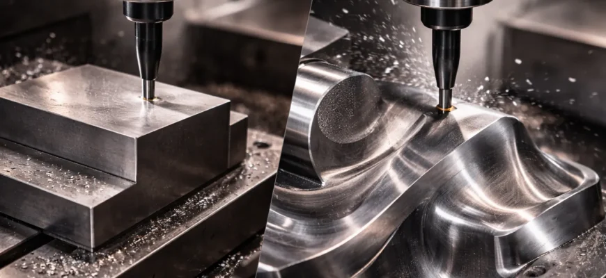
![]() Kellering (right) specializes in sculpting complex 3D contoured surfaces, unlike conventional milling (left), which typically produces simpler, prismatic shapes with flat surfaces.
Kellering (right) specializes in sculpting complex 3D contoured surfaces, unlike conventional milling (left), which typically produces simpler, prismatic shapes with flat surfaces.
At its heart, Kellering is a highly specialized form of machining that focuses on creating intricate, three-dimensional contoured surfaces. Unlike conventional milling, which often deals with planar surfaces or prismatic features, Kellering is about sculpting complex, organic shapes with exceptional accuracy and surface fidelity. This process is critical for manufacturing components where form and surface finish are paramount to performance and functionality. The demand for such precision is escalating across sectors like aerospace, automotive, and medical devices, making Kellering an indispensable skill and technology. The global machining market size is estimated at USD 355.85 billion in 2024 and is expected to reach USD 507.43 billion by 2031, growing at a Compound Annual Growth Rate (CAGR) of 5.20%, underscoring the vast landscape in which Kellering operates source text. The global precision manufacturing service market was valued at USD 127.7 billion in 2024 and is projected to grow to USD 215 billion by 2035, at a CAGR of 4.8% from 2025 to 2035, further highlighting the increasing need for techniques like Kellering source text.
Scope of This Ultimate Guide: What You’ll Learn
This guide aims to be your definitive resource on Kellering. You will learn:
- The fundamental definition and historical context of Kellering, understanding its evolution from mechanical tracers to advanced CNC.
- The core principles and unique characteristics that differentiate Kellering from other machining processes.
- A detailed breakdown of the modern Kellering process, including the essential steps from digital design to physical part.
- Various Kellering toolpath strategies and pattern types, and how to select them for optimal performance based on specific geometries and materials.
- The critical role of tooling and cutting parameters in achieving precision and efficiency in Kellering operations.
- The diverse and impactful applications of Kellering across key industries, showcasing its real-world value.
- The integration of CAM programs and CNC controls in contemporary Kellering workflows.
- The advantages and potential challenges associated with adopting Kellering.
- Best practices and troubleshooting tips for ensuring successful Kellering outcomes.
- The future outlook and emerging trends shaping the field of Kellering.
By the end of this guide, you will have a thorough understanding of Kellering’s capabilities, enabling you to better appreciate its role in manufacturing, make informed decisions about its implementation, and potentially integrate it into your own workflows to better serve your customer requests.
What is Kellering? Defining a Legacy in Form Machining
Kellering is a specialized branch of machining that focuses on the highly accurate reproduction of complex, three-dimensional contoured surfaces. It is often synonymous with 3D contoured surface milling, a process vital for creating shapes that define the functionality and aesthetics of many advanced components.
The Etymology and Origin of “Kellering”
The term “Kellering” originates from the name of the machines developed by the Keller Mechanical Engineering Corp., founded by Sidney and Joseph Keller. These early machines, prevalent in the early to mid-20th century, were designed to precisely replicate a master model by using a tracer stylus that followed the contours of the master. A cutting tool, synchronized with the tracer, would then remove material from a workpiece to mirror the master’s shape. This process was revolutionary for its time, particularly in industries like automotive and aerospace, where complex forms were increasingly required. The legacy of these machines is profound; the design principles of Keller’s machines formed the foundation for modern CAD/CAM and CNC computer programs. Later, the organization‘s technologies were integrated into Pratt & Whitney, further solidifying its impact. In 1989, R. & S. KELLER GmbH was founded, continuing the tradition of advanced form milling.
Core Principles: How Kellering Differs from Conventional Milling
The fundamental difference between Kellering and conventional milling lies in their primary objectives and methodologies. Conventional milling typically involves removing material to create prismatic features, pockets, or simpler contours, often utilizing 2.5D or 3-axis machining. The toolpath is generally defined by a series of linear or circular movements.
Kellering, conversely, is inherently a 3D surface machining process. It relies on continuous, multi-axis (typically 4 or 5-axis simultaneous) movement of the cutting tool relative to the workpiece. This allows for the generation of smooth, flowing contours and complex curvatures. Instead of focusing on discrete features, Kellering is about replicating the entire surface geometry of a master model or a digital design with high fidelity. This capability is crucial for components like turbine blades, impellers, molds, and aerodynamic surfaces, where surface finish and form accuracy directly impact performance.
Key Characteristics: Form Replication and Surface Fidelity
The defining characteristics of Kellering are its unparalleled ability in form replication and surface fidelity.
- Form Replication: Kellering excels at precisely copying complex, three-dimensional shapes. Whether it’s replicating a handcrafted clay model or an intricately designed CAD model, the process ensures that the final part accurately mirrors the input geometry. This is achieved through sophisticated toolpath generation and the continuous coordination of multiple axes on advanced CNC machines.
- Surface Fidelity: Beyond just capturing the overall form, Kellering prioritizes the quality and smoothness of the machined surface. The goal is to minimize surface defects, such as cusps or scallops, and achieve a finish that requires minimal post-processing. This high surface fidelity is critical for parts exposed to high speeds, fluid flow, or requiring specific aesthetic qualities. The ability to achieve such finishes can significantly reduce downstream operations, saving time and cost for the customer.
The Kellering Process: From Master Pattern to Digital Toolpath
The journey from a desired complex shape to a finished part using Kellering has evolved dramatically. While the core principle of replicating a form remains, the methods have transitioned from mechanical tracing to sophisticated digital workflows.
Understanding the Traditional Kellering Process (Historical Context)
Historically, Kellering relied on physical master models. A skilled operator would use a tracer machine, such as the original Keller machines. A stylus would physically follow the contours of a master pattern (often made of wood, plaster, or metal). This tracer’s movement was mechanically linked to a cutting tool, which simultaneously removed material from a workpiece made of the desired manufacturing material. The accuracy was limited by the mechanical linkages, the precision of the master model, and the skill of the operator. While groundbreaking for its time, this process was often time-consuming, labor-intensive, and prone to inaccuracies due to wear and tear on the master and machinery. The organization that pioneered this relied heavily on skilled artisans.
Modern Kellering: The Digital Transformation with CNC Machining
Today, Kellering is intrinsically linked with Computer-Aided Design (CAD), Computer-Aided Manufacturing (CAM), and Computer Numerical Control (CNC) machining. The process begins with a digital 3D model of the desired part, created using CAD software development. This digital model serves as the “master pattern” from which toolpaths are generated by CAM software programs.
The CAM program analyzes the 3D geometry and calculates the optimal cutting paths for the machine tool. This involves sophisticated algorithms that consider tool geometry, material properties, desired surface finish, and machining efficiency. The output of the CAM program is a G-code program, which is a set of instructions that the CNC machine controls interpret and execute. The global CNC machines market size was USD 74.9 billion in 2024, and it is projected to grow by 10.1% during 2025–2032, to reach USD 160.0 billion by 2032, highlighting the pervasive nature of this technology in modern machining source text. This digital transformation has brought unprecedented levels of accuracy, speed, and repeatability to Kellering.
Key Steps in a Modern Kellering Workflow
A typical modern Kellering workflow involves several crucial steps:
- CAD Model Creation/Import: The process starts with a high-quality 3D CAD model of the part. This can be designed from scratch or imported from a customer‘s design files. Data integrity is paramount at this stage.
- CAM Programming: The 3D model is imported into CAM software. Here, the user defines the machining strategy, selects tools, and generates toolpaths. This is the core of Kellering in the digital age.
- Toolpath Generation: The CAM program calculates specific tool movements (e.g., scallop, flowline, spiral) designed to efficiently and accurately machine the complex surfaces. Optimization programs within the CAM suite ensure smooth transitions and minimal tool load variations.
- Simulation and Verification: Before actual machining, CAM software typically offers simulation capabilities. This allows the user to visualize the cutting process, detect potential collisions between the tool, workpiece, and machine components, and verify that the generated toolpath will achieve the desired result. This stage is critical for protection against costly mistakes.
- G-code Generation: Once verified, the CAM program generates the machine-readable G-code. This code contains all the instructions for the CNC machine’s controls, dictating axis movements, spindle speed, feed rates, and coolant activation.
- Machine Setup: The workpiece is secured on the CNC machine, and the correct cutting tools are loaded. The G-code program is then loaded into the machine’s controls.
- Machining Execution: The CNC machine executes the G-code program, precisely moving the cutting tool to sculpt the part. This often involves simultaneous multi-axis machining, where 4 or 5 axes move in coordination.
- Inspection and Finishing: After machining, the part is inspected for dimensional accuracy and surface finish. Depending on the application, minor finishing operations might be required. The efficiency of the Kellering process often minimizes the need for extensive post-processing, saving valuable seconds in the overall production timeline.
Kellering Patterns: Strategies for Complex Surfaces and Forms
The effectiveness of a Kellering operation hinges on the strategic selection and application of toolpath patterns. These patterns dictate how the cutting tool moves across the surface of the workpiece to remove material efficiently and achieve the desired finish.
The Essence of Kellering Toolpath Strategies
The core objective of Kellering toolpath strategies is to optimize material removal rate (MRR), surface finish, and tool life while accurately replicating complex geometries. Unlike conventional milling where toolpaths might be simpler, Kellering requires intricate, continuous movements, often traversing a surface multiple times with overlapping paths. Strategies are designed to maintain consistent tool engagement, minimize rapid changes in direction or cutting force, and ensure that no areas of the surface are left untouched or inadequately machined. The correct programming of these strategies is key to achieving optimal performance.
Common Kellering Pattern Types and Their Application
Several common Kellering toolpath patterns are employed, each suited to different types of geometries and machining operations (roughing, semi-finishing, or finishing):
- Scallop (or Parallel Pass): This is a widely used finishing strategy where the tool moves back and forth across the surface in parallel passes. The distance between these passes, known as the scallop height, directly influences the surface finish. A smaller scallop height results in a smoother finish but requires more passes and longer cycle times. It is effective for finishing relatively simple, large contoured surfaces.
- Flowline: This strategy generates toolpaths that follow the natural contours or flow lines of a surface. It is particularly effective for organic shapes, such as impellers, turbine blades, and body panels, where the toolpath naturally conforms to the curvature. Flowline milling often results in superior surface finish and can improve machining efficiency by maintaining consistent chip load.
- Spiral: A spiral toolpath starts from the center of a surface and moves outwards in an expanding spiral, or vice versa. This pattern is useful for circular or dome-shaped features and can be employed for both roughing and finishing.
- Zig-Zag: Similar to the scallop pattern but with alternating pass directions, the zig-zag pattern can be efficient for covering large areas. It’s often used in roughing operations.
- Offset/Contour: This involves generating toolpaths that are offset from the surface boundary or follow the contour of specific features. It can be used for edge machining or creating detailed features within a larger sculpted surface.
- 3D Pocketing: While not exclusively a Kellering pattern, 3D pocketing is used within Kellering workflows to remove material from enclosed areas or complex cavities, ensuring all regions are accessible.
The selection of the appropriate pattern is crucial for meeting specific customer requirements and achieving the desired performance.
Optimizing Pattern Selection for Specific Geometries and Materials
Optimizing pattern selection involves a nuanced understanding of the geometry being machined and the material properties.
- Geometry: For highly organic and flowing shapes like turbine blades, flowline strategies are often preferred as they mimic the natural curvature, leading to superior surface finish and efficient machining. For flatter, broad contoured surfaces, scallop patterns might be more appropriate. For features with significant depth and complex sidewalls, a combination of strategies might be employed, using pocketing for bulk material removal and flowline or scallop for finishing.
- Materials: Different materials have varying cutting characteristics. For soft, gummy materials like aluminum, high-speed machining (HSM) techniques and specific patterns that manage chip evacuation are crucial to prevent tool buildup and maintain surface finish. For harder materials like titanium or hardened steels, strategies that minimize cutting forces and maintain consistent tool engagement, such as trochoidal milling (a variation of pocketing that maintains constant tool engagement), are vital. These strategies prevent excessive heat buildup and tool breakage, contributing to extended tool life and better performance. The choice of programmatic strategy directly impacts the machining time, often measured in seconds or minutes saved.
Tools and Tooling for Effective Kellering
The success of Kellering is critically dependent on the precise selection and application of cutting tools and the optimization of cutting parameters. This technological synergy ensures both accuracy and efficiency.
The Critical Role of Tool Selection for Kellering Precision
In Kellering, the cutting tool is the direct interface with the material, and its geometry, material composition, and coatings significantly influence the outcome. For complex 3D contoured surfaces, ball-end mills and radius end mills are indispensable.
- Ball-End Mills: These have a hemispherical tip, allowing them to create smooth, contoured surfaces with a consistent stepover. The smaller the stepover (distance between adjacent tool paths), the finer the surface finish, as the cusps left by the tool tip are smaller.
- Radius End Mills: Similar to ball-end mills but with a toroidal (ring-shaped) cutting edge at the tip, these tools offer a larger effective cutting radius, which can improve surface finish and tool life in certain applications compared to a true ball-end mill of the same diameter.
The material of the cutting tool (e.g., high-speed steel, carbide, ceramic, or diamond coatings) must be chosen based on the workpiece material and cutting speeds. Carbide tools are common for their rigidity and wear resistance, while advanced coatings enhance lubricity, reduce heat, and improve tool life.
Specific Tool Types for Kellering Operations
Beyond ball and radius end mills, other tool types may be employed depending on the specific Kellering task:
- Toroidal Cutters: These are specialized tools with a large radius that can create a smooth surface with a reduced number of passes compared to a standard ball-end mill.
- Engraving Tools: For very fine details or text on contoured surfaces.
- Form Tools: For replicating specific profiles or shapes in a single pass, although less common in pure 3D Kellering.
The correct selection ensures that the tool can reach all necessary areas of the part without collision and can withstand the cutting forces involved.
Cutting Parameters: Speed, Feed, and Depth of Cut Optimization for Kellering
Optimizing cutting parameters—spindle speed, feed rate, and depth of cut—is crucial for achieving the desired performance in Kellering. This is where advanced CAM software and machine controls play a vital role.
- Spindle Speed: Dictates how fast the cutting tool rotates. Higher speeds can improve surface finish and MRR in certain materials but also generate more heat.
- Feed Rate: Determines how fast the tool moves through the material. It’s often expressed in inches per minute (IPM) or millimeters per minute (mm/min). A balanced feed rate ensures consistent chip load, preventing tool breakage and overheating.
- Depth of Cut (DOC): This refers to the axial depth of the material removed in a single pass. For effective Kellering, especially with hard materials or smaller tools, shallow depths of cut are often preferred, especially in finishing passes, to maintain tool life and surface quality.
- Width of Cut (WOC) or Stepover: This is the radial distance the tool moves between adjacent passes. In Kellering, a smaller stepover results in a smoother surface finish, but increases machining time. CAM programs often allow for dynamic stepover adjustments to optimize for different areas of the part.
Advanced CAM software and CNC controls enable High-Speed Machining (HSM) techniques. HSM involves using higher spindle speeds and feed rates with shallow depths of cut and optimized stepovers. This approach leads to significantly reduced cycle times, improved surface finishes, less heat generation, and extended tool life. The global metal cutting tools market was valued at USD 46.6 billion in 2024 and is expected to grow from USD 48.8 billion in 2025 to USD 78.4 billion in 2034, at a CAGR of 5.4%, highlighting the crucial and evolving nature of cutting tools and parameters source text. Milling tools captured 38% of 2024 global revenue in the metal cutting tools market, indicating their significant role in these processes source text.
Machine Tool Requirements for High-Performance Kellering
Achieving high-performance Kellering demands specific machine tool capabilities. The most critical requirement is advanced multi-axis capability, typically 4-axis or 5-axis simultaneous motion.
- 5-Axis Capability: Allows the cutting tool to approach the workpiece from virtually any angle. This is essential for machining complex, undercutting, or highly contoured features without needing to reposition the part multiple times or resort to special tooling.
- Rigidity and Accuracy: The machine must be exceptionally rigid to withstand cutting forces without deflection, ensuring dimensional accuracy and a smooth surface finish. High-precision linear guideways and robust machine construction are paramount.
- High-Speed Spindles: For HSM strategies, high-speed spindles (often 10,000 RPM or higher) are necessary to achieve optimal cutting speeds and efficient material removal.
- Advanced CNC Controls: The machine’s CNC controls must be sophisticated enough to interpret complex G-code programs generated by CAM software, execute smooth multi-axis coordinated movements, and often feature look-ahead capabilities to anticipate and manage toolpath trajectories efficiently.
The investment in such machinery and CAM software is significant, but it is often a prerequisite for organizations aiming to excel in complex form machining and meet demanding customer requirements.
Applications of Kellering in Modern Manufacturing
Kellering’s ability to produce intricate, high-precision 3D forms makes it indispensable across a wide spectrum of modern manufacturing industries. Its application drives innovation, improves component performance, and enables the creation of products that were previously impossible to manufacture.
Aerospace Components: Intricate Aerofoils and Structural Forms
The aerospace industry relies heavily on Kellering for manufacturing critical components. This includes:
- Turbine Blades and Blisks (Blade Disks): The complex aerofoil shapes of turbine blades are prime examples of Kellering’s application. Achieving the precise curvature and smooth surface finish is vital for aerodynamic efficiency, fuel economy, and engine performance.
- Impellers: Used in pumps and compressors, impellers require intricate internal passageways and vanes that Kellering can accurately reproduce.
- Structural Components: Complex wing sections, fuselage parts, and other load-bearing structures often feature complex curvatures and lightweight designs that benefit from 5-axis Kellering.
Materials like titanium, Inconel, and high-strength aluminum alloys are commonly machined, requiring specialized Kellering strategies. The aerospace parts manufacturing market size stood at USD 1.02 trillion in 2025 and is projected to reach USD 1.39 trillion by 2030, translating into a 6.39% CAGR, underscoring the immense demand for these precision components source text.
Automotive Industry: Dies, Molds, and Prototype Development
In the automotive sector, Kellering plays a crucial role in both production tooling and advanced development.
- Molds and Dies: Creating molds for injection molding or die-casting of complex automotive parts (e.g., engine covers, dashboards, body panels) often involves intricate cavity and core designs that are perfectly suited for Kellering. The global die and mould products market was valued at USD 53.4 billion in 2024 and is projected to reach USD 86.9 billion by 2033, growing at a CAGR of 5.5% from 2025 to 2033, highlighting its importance source text.
- Engine Components: Components like piston domes, combustion chambers, and cylinder heads require precise contoured surfaces for optimal combustion efficiency and performance.
- Prototype Development: For new vehicle designs, rapid prototyping of complex body panels or functional components often utilizes Kellering to quickly produce accurate models for testing and validation. North American companies ordered 17,635 robots valued at $1.094 billion in the first six months of 2025, with automotive OEMs leading with a 34% year-over-year increase in units ordered, demonstrating the industry’s drive towards advanced automation and precision manufacturing source text.
Tool and Die Making: The Traditional Stronghold of Kellering
The tool and die industry is perhaps the most traditional and significant user of Kellering. The complexity of molds for plastics, metals, and composites, as well as the intricate designs of stamping and forming dies, demands the precision and surface quality that Kellering provides. Achieving exact replication of master patterns or CAD designs is paramount for the functionality and longevity of these tools. This sector directly benefits from the high performance and accuracy Kellering offers, ensuring the quality of mass-produced goods.
Medical Devices: Precision Forms for Implants and Instruments
The medical field requires an exceptionally high degree of precision and biocompatibility, making Kellering an essential technique.
- Implants: Custom orthopedic implants (hip, knee, dental) are often manufactured using Kellering to match patient-specific anatomy, ensuring a precise fit and optimal performance.
- Surgical Instruments: Complex surgical tools, such as those with articulated joints, micro-scalpels, or specialized gripping surfaces, benefit from the intricate geometries achievable with Kellering.
- Prosthetics and Orthotics: Highly customized devices that require precise anatomical replication can be efficiently produced using Kellering.
The demand for tight tolerances and smooth surfaces is non-negotiable, as these directly impact patient safety and therapeutic outcomes.
Consumer Electronics and Product Design: Complex Housings and Aesthetics
In consumer electronics and product design, Kellering is employed to create visually appealing and highly functional housings and components.
- Device Housings: Complex ergonomic designs for smartphones, laptops, gaming consoles, and wearables often feature intricate curves and seamless integration that are best achieved through Kellering.
- Aesthetic Components: For high-end consumer goods, the surface finish and form are critical to the perceived value and brand identity. Kellering allows designers to bring their most ambitious aesthetic visions to life.
- Small-Scale Precision Parts: The trend towards miniaturization in electronics means that even small components require precise shapes for functional integration.
These applications showcase Kellering’s versatility, extending its impact beyond traditional heavy industries into everyday consumer products.
Modern Kellering: CAM Software and CNC Integration
The advent of digital technologies, particularly CAM software and advanced CNC controls, has revolutionized Kellering, transforming it from a mechanical replication process into a sophisticated digital workflow.
Evolution from Manual Tracing to Digital Toolpaths
The transition from manual tracing machines to CAD/CAM-driven CNC machining represents a paradigm shift. Early Kellering relied on physical masters and mechanical linkages, which were prone to wear, inaccuracies, and limitations in complexity. Modern Kellering begins with a digital 3D model, eliminating the need for physical masters and enabling unprecedented levels of precision and design freedom. CAM software programs are now capable of generating incredibly complex toolpaths, optimizing for efficiency, performance, and surface finish in ways that were previously unimaginable. This digital workflow ensures that a customer‘s design is translated into a physical part with a high degree of fidelity, managed by sophisticated computer programs.
Key Features of CAM Software for Kellering
Modern CAM software programs offer a suite of features essential for effective Kellering:
- Advanced 3D Modeling Capabilities: While often imported, some CAM suites include basic modeling tools for creating or modifying surfaces.
- Sophisticated Toolpath Generation Strategies: Access to a wide range of Kellering-specific patterns (scallop, flowline, spiral, etc.) with customizable parameters.
- High-Speed Machining (HSM) Options: Algorithms designed for efficient material removal at high spindle speeds with shallow depths of cut, crucial for advanced Kellering.
- Collision Detection and Avoidance: Built-in tools to simulate the machining process and identify potential collisions between the tool, spindle, workpiece, and fixtures, ensuring protection of both the workpiece and the machine.
- Stock Awareness and Optimization: The program understands the remaining material (stock) and adjusts toolpaths to optimize for efficiency, reduce air cutting, and ensure consistent cutting conditions.
- Surface Finish Control: Parameters to manage stepover, scallop height, and tool engagement to achieve desired surface qualities, often measured in microns or micro-inches.
- G-code Post-processing: The ability to generate specific G-code programs tailored to a particular CNC machine brand and model and its controls.
- Simulation and Visualization: Realistic rendering of the machining process, allowing users to verify toolpaths and cycles before committing to the shop floor.
The continuous software development in this area means that CAM programs are constantly evolving, offering new efficiencies and capabilities that push the boundaries of what’s possible in machining.
The Role of CNC Controls in Kellering
CNC controls are the brains of the machining operation. For Kellering, their importance cannot be overstated. Modern CNC controls (from manufacturers like Siemens, Fanuc, Heidenhain) must be capable of:
- Interpreting Complex G-code: Handling intricate multi-axis toolpath commands generated by CAM software.
- High-Speed, High-Precision Motion Control: Executing smooth, coordinated movements across multiple axes simultaneously to follow complex curves accurately.
- Look-Ahead Functionality: Processing upcoming blocks of G-code to anticipate movements and ensure continuous, fluid motion, minimizing stops and jerky movements.
- Tool Center Point (TCP) Control: For 5-axis machines, accurately calculating the tool tip position regardless of the tool’s orientation.
- Machine Parameter Management: Allowing the user to fine-tune machine performance characteristics, such as acceleration/deceleration profiles, to match the requirements of the CAM program.
The seamless integration between the CAM software program and the CNC machine’s controls is paramount for successful Kellering, ensuring that the digital design is accurately translated into a physical part with high performance.
Advantages and Challenges of Kellering
While Kellering offers significant advantages for complex machining, its implementation also presents challenges that organizations must consider.
Key Benefits of Kellering
The adoption of Kellering brings about numerous benefits that contribute to improved product quality, efficiency, and competitiveness.
- Superior Surface Finish: Kellering excels at producing exceptionally smooth contoured surfaces, often reducing or eliminating the need for secondary finishing operations. This can save significant time and cost. Achieving surface roughness values as low as 0.4 µm is possible with meticulous parameter selection.
- Enhanced Precision and Accuracy: The combination of advanced CAD/CAM software programs, precise tooling, and multi-axis CNC machining allows for the creation of parts with very tight tolerances, often within ±0.02 mm, and even tighter (±0.005 mm or less) when required.
- High Material Removal Rate (MRR): Optimized Kellering strategies, particularly those employing HSM, can achieve remarkably high MRR. For instance, in aluminum, rates exceeding 50 mm³/min per mm of tool diameter are achievable, drastically reducing machining times.
- Extended Tool Life: By employing optimized cutting strategies, balanced tool loading, and appropriate cutting parameters, tool life can be significantly extended, often by 50-100%, reducing tooling costs.
- Reduced Cycle Times: The efficiency of modern Kellering techniques, especially with HSM and optimized toolpaths, can lead to substantial reductions in overall cycle times, often by 30-50% for complex aerospace components. This translates to faster delivery for the customer and increased throughput.
- Capability for Complex Geometries: Kellering is the go-to method for manufacturing parts with intricate, organic, or undercutting features that are impossible to create with conventional machining methods.
Potential Challenges and Considerations
Implementing Kellering effectively requires addressing several potential challenges:
- High Initial Investment: Advanced 5-axis CNC machines, sophisticated CAM software, and high-quality tooling represent a significant capital investment.
- Skilled Operator and Programmer Requirements: Operating and programming advanced Kellering systems demands highly skilled personnel with expertise in CAD/CAM, CNC machining, and an understanding of cutting mechanics and material science. This requires ongoing training and development for the user.
- Complex Software and Programming: While powerful, CAM software programs can have steep learning curves. Developing efficient and reliable toolpaths for complex parts requires considerable experience.
- Setup Times: While cycle times can be reduced, initial setup for complex 5-axis Kellering jobs can sometimes be lengthy, involving precise fixture setup and tool orientation.
- Data Security and IP Protection: The digital nature of modern Kellering workflows involves sensitive CAD data. Ensuring robust protection of intellectual property against cyber threats or unauthorized access is crucial. Utilizing secure cloud storage and access protocols can help, but requires careful implementation.
Best Practices and Troubleshooting for Kellering
Adhering to best practices and understanding common troubleshooting scenarios are vital for consistently achieving high-quality results with Kellering.
Essential Best Practices for Successful Kellering
Implementing Kellering successfully relies on a disciplined approach to planning and execution.
- Invest in Quality CAD Models: Ensure the initial 3D CAD design is flawless, watertight, and represents the intended geometry accurately. Clean data is the foundation of good machining.
- Choose the Right CAM Software and Tools: Select CAM software programs that are robust, have strong Kellering capabilities, and are compatible with your CNC machine controls. Invest in high-quality, well-maintained cutting tools.
- Master Toolpath Strategy Selection: Thoroughly understand the different Kellering patterns and their suitability for various geometries and materials. Don’t hesitate to use simulation to test different strategies.
- Optimize Cutting Parameters Carefully: Leverage HSM principles where appropriate. Start with conservative parameters and incrementally adjust based on machining feedback and surface performance. Understand the trade-offs between speed, finish, and tool life.
- Simulate, Simulate, Simulate: Always use CAM software to simulate the entire machining process before cutting metal. This catches errors, optimizes toolpaths, and provides valuable insights.
- Maintain Machine Tools: Regular maintenance of CNC machines, including calibration and lubrication, is crucial for maintaining accuracy and performance.
- Effective Communication: Foster clear communication between designers, programmers, operators, and the customer to ensure all requirements are understood and met. This enhances customer service and project success.
Common Troubleshooting Scenarios and Solutions
Despite best practices, issues can arise. Here are some common troubleshooting scenarios:
- Poor Surface Finish (e.g., visible cusps, tool marks):
- Cause: Insufficient tool overlap (stepover too large), incorrect tool selection, worn tooling, or suboptimal cutting parameters.
- Solution: Reduce stepover, use a smaller or more appropriate tool, replace worn tooling, adjust feed rate and spindle speed for smoother cutting.
- Tool Breakage:
- Cause: Excessive depth of cut or width of cut, insufficient coolant, material inconsistencies, or poor toolpath strategy (e.g., sudden changes in cutting load).
- Solution: Reduce DOC/WOC, ensure adequate coolant flow, review toolpath for aggressive movements, check for material defects. For hard materials, consider trochoidal milling strategies to maintain consistent chip load.
- Dimensional Inaccuracies:
- Cause: Machine calibration issues, excessive cutting forces causing deflection, incorrect fixture setup, or inaccuracies in the CAM program.
- Solution: Re-calibrate the machine, review toolpath for potential deflection points and adjust parameters, ensure rigid fixturing, verify CAM program and post-processor.
- Longer Than Expected Cycle Times:
- Cause: Inefficient toolpath strategies, overly conservative cutting parameters, excessive air cutting, or underutilization of HSM techniques.
- Solution: Re-evaluate toolpath strategies for better coverage and overlap, increase cutting parameters where feasible and safe, optimize toolpaths to minimize non-cutting moves, leverage HSM capabilities. Saving even a few seconds per pass can add up to significant time savings.
By understanding these troubleshooting tips, users can more effectively diagnose and resolve issues, ensuring the consistent delivery of high-quality Kellering work that meets customer expectations.
Conclusion: The Enduring Value of Kellering
Kellering, with its roots in mechanical replication and its evolution into a sophisticated digital process, remains a cornerstone of precision machining. Its ability to sculpt complex, three-dimensional contoured surfaces with unparalleled accuracy and fidelity is indispensable for industries pushing the boundaries of innovation. From the aerodynamic efficiency demanded in aerospace to the intricate forms required in medical devices and consumer electronics, Kellering empowers manufacturers to create components that define modern performance and aesthetics. The integration of advanced CAD/CAM software programs, high-performance CNC controls,