Kellering in Machining: Definition, Process, Surface Pattern, Tools, and Applications
In simple terms: Where standard milling moves a cutter in flat, linear paths to make flat features, kellering moves the cutter in a three-dimensional following path to machine sculpted, flowing, or dome-shaped surfaces — shapes that straight-line milling cannot produce.
Quick answers:
What Is Kellering in Machining?
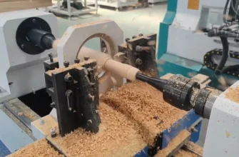
Kellering is a three-dimensional contour milling operation in which a cutting tool — typically a ball-nose end mill or round-nosed profiling cutter — traces a controlled path across a workpiece surface to generate complex curved geometry.
The defining characteristic of kellering is that the cutter path is not planar. Instead of moving in straight-line passes at constant Z-depth, the tool follows the topography of the intended surface in all three axes simultaneously — X, Y, and Z move together in a continuously changing relationship that sculpts the final form into the material.
Why the term is niche and unfamiliar to many readers
Kellering is an industry-specific term most commonly used in die and mold shops, piston manufacturing, and heavy tooling environments. Younger engineers trained in modern CAM environments often know the concept perfectly well but refer to it as 3D contour milling, sculptured surface machining, or 3-axis surface finishing — without knowing the original Keller-derived terminology. This vocabulary gap is why the term appears ambiguous in online search results and why significant SERP confusion exists around it.
The machining concept it describes, however, is entirely modern, widely practiced, and critically important to advanced manufacturing.
Kellering vs. Knurling: The Critical Difference
This disambiguation must be made clearly and early, because search results regularly conflate these two completely unrelated processes.
What knurling is
Knurling is a surface texturing operation performed on a lathe in which hardened rolling wheels are pressed against a rotating cylindrical workpiece to cold-form a raised diamond, straight, or angled pattern into the surface. The purpose is to:
- Create grip surfaces on handles, knobs, and adjustment screws
- Slightly increase the OD of a shaft for a press-fit interference
- Add aesthetic surface texture to turned components
Knurling is a forming process — it displaces material, does not remove it, and operates on the outer diameter of round parts in a lathe environment.
What kellering is
Kellering is a 3D milling process performed on a vertical or horizontal machining center (or historically a tracer mill). It:
- Removes material through cutting, not forming
- Operates in three simultaneous axes
- Produces flowing, curved, and sculpted surfaces
- Is used on dies, molds, pistons, and complex components
- Has no relationship to cylindrical surfaces or grip patterns
Why the confusion happens
The two words have superficial phonetic similarity. In non-specialist search contexts, both are associated with “machining” and “surface pattern.” Neither is commonly taught in standard introductory machining curricula, which creates a vocabulary vacuum that generates conflation.
The clear rule: If the discussion involves a lathe, cylindrical parts, and textured grip — it is knurling. If the discussion involves a milling machine, three-axis motion, and complex curved surfaces — it is kellering.
Historical Background of Kellering
The Keller Machine Company
The term kellering derives directly from the Keller Machine Company, a US manufacturer that produced tracer-controlled milling machines from the early-to-mid twentieth century. Keller machines were among the most important die-making and mold-making tools of their era, solving a problem that conventional machining could not address: how to reproduce a complex three-dimensional shape from a master model directly into metal.
Tracer-controlled milling: the original mechanism
Before CNC, the only way to machine a smoothly curved 3D surface was to follow a physical reference. Keller’s tracer mills worked like this:
- A physical master model (a prototype, casting, or sculptured template) was placed alongside the workpiece on the machine
- A tracer stylus — a mechanical probe — was pressed lightly against the surface of the master model
- As the stylus moved across the model’s contour, its deflections were converted into hydraulic or electromechanical signals
- These signals drove the cutter in precisely the same three-dimensional path across the workpiece that the stylus traced on the model
- The workpiece was machined to an accurate replica of the master
This process was revolutionary for die and mold making. Previously, die cavities with complex organic curves required intensive hand-fitting and filing by highly skilled die sinkers. Keller’s tracer mills automated the replication of those shapes with far better consistency, speed, and repeatability.
From tracer milling to CNC
As numerical control and later CNC became available from the 1960s onward, physical master models were progressively replaced by mathematical surface descriptions — first as digitized point clouds from the tracer path, then as CAD geometry. The machine mechanics changed (servo-driven ballscrews replaced hydraulic tracers), but the fundamental intent remained: machine a complex three-dimensional surface accurately and repeatably.
The term “kellering” persisted in shops that had used Keller equipment, and then survived as a general descriptor for this class of contour surface milling work — much like how “Hoover” persisted as a general term for vacuum cleaners in British English.
How the Kellering Process Works
Step 1 — Define the 3D contour
The target surface geometry is established. Historically, this was a physical master model (wood, plaster, zinc alloy, or precision casting) positioned on the tracer mill table. In modern CNC practice, this is a 3D CAD surface model created in software such as CATIA, SolidWorks, NX, or Fusion 360.
Step 2 — Generate the toolpath
In tracer milling, the “toolpath” was generated dynamically and in real time by the mechanical stylus following the master. In modern CAM (Computer-Aided Manufacturing) software, the programmer selects a 3D surface finishing strategy — parallel passes, scallop constant step-over, contour following, or radial — and the software calculates a precise three-dimensional cutter path that covers the entire surface within specified tolerance and step-over parameters.
Step 3 — The cutter follows the 3D contoured path
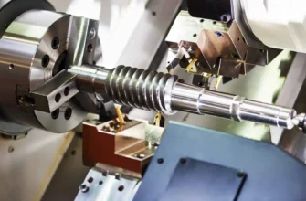
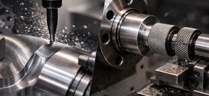
The machining center executes the toolpath: all three axes — X, Y, and Z — move simultaneously in coordinated motion. The cutting tool, typically a ball-nose end mill, maintains contact with the target surface geometry throughout the pass. Unlike flat-end milling with fixed Z-depths, the tool rises and falls continuously, following every curve, dome, valley, and transition in the surface.
Step 4 — Material is removed progressively
Kellering is rarely performed in a single pass. The process typically involves:
- Roughing: A larger-diameter end mill (flat or bull-nose) removes the bulk of material in a stepped approximation of the final form, leaving a defined amount of stock (typically 0.3–1.0 mm) on all surfaces
- Semi-finishing: Reduces remaining steps and irregular stock with a smaller tool, bringing the surface closer to final form
- Finishing: A small ball-nose end mill (often 6–16 mm diameter) follows the final toolpath at fine step-over (0.1–0.5 mm), producing the final contoured surface
Step 5 — The final contoured surface is formed
The result is a three-dimensionally curved surface that matches the CAD model (or original master) within the specified tolerance — typically ±0.02–0.1 mm in die and mold applications, and tighter in high-precision aerospace contexts.
Surface Pattern and Surface Finish
The characteristic scallop pattern
Kellering with a ball-nose end mill leaves a distinctive and well-understood surface pattern: scallop marks — a series of overlapping curved ridges corresponding to the step-over distance between adjacent cutter passes.
These scallops are an unavoidable geometric consequence of the ball-nose geometry. If the cutter radius is R and the step-over distance is S, the scallop height (the peak-to-valley distance of the ridges) is approximately:
h≈8RS2
This relationship tells machinists exactly how to trade off cycle time (determined largely by step-over) against surface finish (determined by scallop height).
Practical surface finish control
| Step-over (% of tool diameter) | Scallop height (typical) | Cycle time impact |
|---|---|---|
| 50% | Rough — visible ridges | Fast |
| 20–30% | Semi-finish | Moderate |
| 5–10% | Fine finish (Ra 0.8–1.6 μm typical) | Slow |
| 1–3% | Near-polished (Ra < 0.4 μm possible) | Very slow |
Finishing passes in die and mold machining are typically run at 5–10% step-over, after which hand polishing or EDM finishing may be applied to reach final mold cavity finish standards.
How this differs from knurling’s surface pattern
Knurling produces a precisely geometric, repeating diamond or linear texture by cold-forming — the pattern is consistent, uniform, and intentional for grip. Kellering’s scallop pattern is a manufacturing byproduct of the toolpath and tool geometry, minimized and controlled rather than displayed as a feature. One is a design intent; the other is a machining artifact to be managed.
Tools Used in Kellering
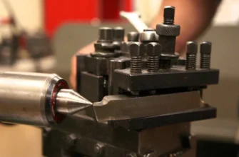
Ball-nose end mill (primary tool)
The ball-nose end mill is the foundational tool for kellering and all 3D contour surface milling. Its hemispherical cutting end means that regardless of the tool-surface contact angle — which changes continuously as the cutter traverses a curved surface — the cutting radius at the contact point remains constant (equal to the ball radius).
This geometric consistency is what allows a ball-nose mill to produce a predictable scallop pattern and maintain surface accuracy across changing surface inclinations.
Key specifications for kellering:
- Diameter: typically 6–20 mm for finishing; 16–32 mm for semi-finishing
- Coatings: TiAlN, AlCrN, or DLC coatings for heat resistance and reduced friction
- Substrate: Solid carbide (small to medium diameters) or carbide inserts (larger diameters)
- Number of flutes: 2-flute for slotting/deep cavities; 4-flute for finishing on open surfaces
Bull-nose (corner-radius) end mill
The bull-nose or toroidal end mill has a flat face with a defined corner radius. Used in semi-finishing and roughing passes preceding ball-nose finishing, it removes material faster than a ball-nose while leaving less stock than a flat end mill, reducing the load on the finishing pass.
Taper ball-nose end mill
For deep cavities, die pockets, and undercut profiles, taper ball-nose tools provide the required reach while maintaining rigidity — a straight long-reach tool of the same diameter would deflect under the lateral forces encountered in deep finishing passes.
Machine requirements
Kellering requires a machine capable of simultaneous three-axis coordinated motion with:
- Sufficient rigidity to resist cutting forces during 3D surface passes
- High-quality ball screw or linear drive systems for positional accuracy in all three axes
- Adequate spindle speed range (8,000–30,000 RPM for small-diameter ball-nose finishing passes)
- CNC controller capable of executing high-density G-code programs (3D surface files can contain tens of thousands of individual moves)
- High-speed machining (HSM) capability for modern production-rate 3D contour finishing
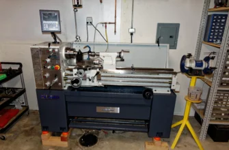
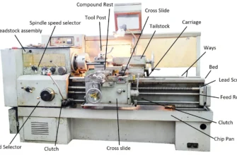
Appropriate machines:
- CNC vertical machining centers (VMC) — most common for dies, molds, and medium-large parts
- CNC horizontal machining centers (HMC) — for large palletized die work and aerospace structures
- 5-axis machining centers — for undercuts, compound-angle surfaces, and eliminating secondary setups on complex parts
- Historically: Keller tracer mills and similar hydraulic/electromechanical contour tracing machines
Toolpath, CAM, and CNC Control
How CAM software generates kellering-equivalent toolpaths
Modern CAM software (Mastercam, Hypermill, NX CAM, Fusion 360 CAM, PowerMill) contains dedicated 3D surface finishing strategies that replicate and extend what Keller tracer mills did mechanically:
- Parallel finishing (Z-level or planar): Cutter traverses the surface in parallel straight-line passes at fine step-over, with Z adjusting continuously to follow the surface. Simple to program, predictable finish.
- Contour finishing (constant Z): Cutter follows level-line contours of the surface at each Z-height — efficient for steep-walled features, less effective on shallow slopes.
- Scallop / constant step-over finishing: CAM calculates paths that maintain a constant step-over across the entire surface regardless of inclination angle — the most uniform finish strategy for complex compound-curvature surfaces.
- Radial / spiral finishing: Used on rotationally approximate surfaces like piston domes — the cutter spirals outward from the dome center.
- Pencil milling / corner finishing: Small-diameter tool traces internal fillet radii and transitions that larger tools cannot reach.
The relationship between CAM strategy and surface quality
The entire point of CAM-driven kellering is to give the programmer full control over the trade-off between cycle time and surface quality. By adjusting step-over, tool diameter, feed rate, and toolpath type, the machinist can dial in exactly the scallop height and surface finish required — something tracer mills could only achieve by changing the physical pass density through mechanical adjustment.
High-speed machining integration
Modern kellering is typically executed under HSM (High-Speed Machining) conditions: light depth of cut, high spindle speed, high feed rate, with constant engagement managed by the CAM software. This approach:
- Reduces cutting forces (protecting the machine and the thin-wall die sections)
- Generates less heat at the workpiece surface
- Produces better surface finish with fewer finishing passes
- Extends tool life by avoiding thermal overload
How Kellering Differs from Standard Milling
| Factor | Standard (Conventional) Milling | Kellering (3D Contour Milling) |
|---|---|---|
| Toolpath geometry | Straight-line at constant Z-depth | Three-axis simultaneous curved path |
| Surface geometry produced | Flat planes, simple steps, pockets | Domes, free-form curves, sculpted profiles |
| Primary cutter type | Flat-end mill | Ball-nose or bull-nose end mill |
| Applicable geometries | Prismatic (angular, flat) features | Complex, compound-curvature surfaces |
| Toolpath complexity | Simple — single-axis primary motion | Complex — all three axes move simultaneously |
| CAM requirement | Simple; even manual programming possible | CAM software practically mandatory for quality paths |
| Surface finish mechanism | Flat passes, minimal scallop | Controlled scallop pattern from ball-nose geometry |
| Setup complexity | Lower — stable Z reference | Higher — surface accuracy depends on workpiece datum and setup precision |
| Typical applications | Slots, pockets, stepped features, bores | Dies, molds, pistons, aerospace contours, complex tooling |
The single most important difference: Standard milling makes features that can be fully described by their cross-section at a fixed depth. Kellering makes features that can only be described by their full three-dimensional surface equation. This distinction drives everything else — tool choice, toolpath strategy, machine requirements, and cycle time.
Applications of Kellering
Piston crown and dome machining
The combustion-side face of a piston — the crown — is rarely flat. In performance engines, diesel engines, and direct-injection applications, the piston crown features precisely shaped domes, bowls, reliefs for valve clearance, and complex compound curves that define the combustion chamber geometry.
These shapes cannot be milled with flat-end tools and straight passes. Kellering with ball-nose end mills and 3D contour toolpaths produces the exact geometry required, with the surface finish and dimensional accuracy needed for combustion efficiency and piston longevity. This is one of the oldest and most established applications of the kellering process.
Forging dies
A forging die cavity must precisely replicate the net shape of the forged component — often complex shapes such as connecting rods, crankshafts, turbine blade blanks, and structural aircraft forgings. These cavities have deep pockets, flowing radii, draft angles, and compound-curvature surfaces throughout.
Before CNC, Keller tracer mills were the primary production method for forging die cavities. A master model was machined or hand-sculpted, and the Keller machine duplicated it into the die block. Today, CNC kellering directly from CAD geometry has replaced the master model but uses the same fundamental three-axis surface-following principle.
Plastic injection molds
Mold cavities for consumer products, automotive interior components, medical housings, and electronic enclosures contain highly complex sculptured surfaces, fine surface finish requirements (as the mold surface directly transfers to the plastic part), and deep cavities with multiple internal features.
CNC kellering — finishing passes with small ball-nose end mills at fine step-over — produces the cavity surface to the finish level at which polishing can begin. Surface finish from the machining process directly determines the polishing labor required and the final mold cost.
Stamping dies and draw dies
Sheet metal stamping dies for automotive body panels, appliance components, and structural stampings have large, gently curved three-dimensional draw surfaces that form the metal sheet into the required shape. These surfaces extend over hundreds or thousands of square millimeters and must be machined to high accuracy and smooth finish to achieve consistent material flow during stamping.
Kellering on large CNC machining centers produces these draw surfaces precisely, replacing the former combination of profiling and extensive hand-fitting that die-makers performed manually.
Aerospace structural components and contoured panels
Aircraft wing skins, fuselage structural panels, engine nacelle components, and turbine blade platforms contain complex compound-curvature surfaces defined by aerodynamic requirements. These surfaces must be machined to tight tolerance in aluminum alloys, titanium alloys, and composites.
Five-axis CNC kellering — where the tool can also tilt for optimal cutting angle on the surface — is the standard method for producing these aerospace contoured components, providing dimensional accuracy to ±0.05–0.1 mm over large surface areas.
Automotive performance parts and heads
Cylinder head combustion chamber porting, intake manifold runners, and custom performance component profiles are machined using kellering-style 3D contour passes. The geometry of these surfaces directly affects fluid dynamics and engine performance — precision three-axis milling to the designed CAD surface is the only way to achieve the intended form.
Advantages of Kellering
- Geometry freedom: Machines any three-dimensionally complex surface that geometry permits — not limited to prismatic or axis-aligned features.
- Replication accuracy: From Keller tracer mills copying physical masters to modern CNC following CAD geometry, the core strength has always been faithful, accurate replication of the intended surface form.
- Repeatability: CNC-driven kellering produces the same surface on every part, every shift — critical for high-volume die production and matched tooling applications.
- Integration with the full manufacturing process: CAD surface data flows directly into CAM, directly into the CNC program, and directly into the part — eliminating the intermediate hand-crafting and fitting steps that dominated pre-Keller die production.
- Scalability: The same CNC kellering process scales from a 50 mm piston dome to a 2,000 mm automotive stamping die surface — with adjustments to machine size, tool diameter, and step-over parameters.
- Surface finish control: By tuning step-over and tool selection, the machinist directly controls the surface finish output — enabling the correct balance between machined surface quality and finishing/polishing labor.
Limitations and Challenges
Programming and CAM complexity
Three-dimensional contour toolpaths generate very large CNC programs — tens of thousands of individual coordinate positions — that cannot be written by hand and require capable CAM software, a skilled programmer, and significant compute time for complex surfaces. CAM licensing, training, and workstation investment are real costs in the kellering process.
Machine requirements
Not every machining center is suited for kellering. The machine must have:
- Sufficient rigidity for long finishing passes under lateral cutting forces
- Accurate, low-backlash axes for three-axis simultaneous motion
- High enough spindle speed for small-diameter ball-nose finishing tools
- A controller fast enough to process dense high-speed toolpath data without “data starvation” (where the controller processes moves faster than data arrives, causing hesitation and surface marks)
Older or lower-specification machines produce inferior surface finish and dimensional accuracy on kellering operations, even with identical toolpaths.
Cycle time
Fine-step-over finishing passes on large surfaces are inherently slow. A high-quality surface on a large automotive die cavity may require many hours of finish-pass machining, even at high feed rates. Cycle time is one of the primary cost drivers in mold and die production, and reducing it without sacrificing surface quality is a constant engineering challenge.
Tool wear sensitivity
Ball-nose end mills wear at the tip — the smallest-diameter, lowest-surface-speed region of the tool. As the tip wears, the effective cutting geometry changes, causing small but cumulative dimensional errors across the surface. Tool wear monitoring, insert indexing, and consistent tool change intervals are essential for maintaining surface quality across long kellering programs.
Surface finish sensitivity to toolpath parameters
Small changes in step-over, feed rate, spindle speed, or tool runout produce visible differences in surface finish that must then be corrected in polishing — adding time and cost. The interaction between toolpath parameters and surface outcome requires experience and measurement to optimize for each material and surface type.
FAQ: People Also Ask
What is kellering in machining?
Kellering is a three-dimensional contour milling process in which a cutting tool follows a complex curved path in all three axes simultaneously to machine sculpted surfaces — such as piston domes, die cavities, and mold surfaces. It originated with tracer-controlled Keller milling machines that followed physical master models, and today is executed via CNC machining centers programmed with CAM software.
Is kellering the same as knurling?
No. Knurling is a lathe-based surface texturing operation that cold-forms a grip pattern (diamond or straight) onto a cylindrical surface. Kellering is a milling process that removes material in three-dimensional contoured paths to produce curved precision surfaces. They are completely unrelated processes with different tools, machines, outcomes, and applications.
What kind of surface does kellering produce?
Kellering produces a three-dimensionally curved surface with a characteristic scallop pattern — overlapping curved ridges corresponding to the step-over distance between adjacent cutter passes. The height of these scallops (and therefore the surface roughness) is controlled by reducing step-over or increasing the cutter radius. Fine-step-over finishing passes can produce surfaces smooth enough to polish to mirror finish.
What tools are used in kellering?
The primary tool is a ball-nose end mill — a milling cutter with a hemispherical cutting tip that maintains consistent cutting geometry across changing surface inclinations. Bull-nose (corner radius) end mills are used for semi-finishing, and taper ball-nose tools are used for deep cavity reach. All require CNC machining centers capable of simultaneous three-axis motion.
Is kellering a type of milling?
Yes. Kellering is a specific subset of milling — specifically, three-axis (or more) contour surface milling of complex curved geometry. It differs from standard milling in that the cutter path moves in all three axes simultaneously rather than in straight-line passes at constant depth.
Where is kellering used in manufacturing?
Kellering is primarily used in: piston crown and dome machining, forging die production, plastic injection mold machining, stamping and draw die production, aerospace contoured structural components, and automotive performance parts such as cylinder heads and intake manifolds.
How does kellering differ from conventional milling?
Conventional milling uses straight-line cutter paths at constant Z-depth to produce flat, stepped, or prismatic features using flat-end mills. Kellering uses three-axis simultaneous cutter motion to follow complex curved surfaces, using ball-nose end mills, producing free-form geometry that conventional milling cannot achieve. The toolpath complexity, machine requirements, CAM dependency, and applicable geometries are fundamentally different.
Conclusion
Kellering is one of the most important — and least clearly explained — processes in precision manufacturing. It represents the direct lineage from the tracer-controlled Keller milling machines that transformed die and mold making in the twentieth century to the CNC-driven three-axis contour finishing operations that underpin the production of pistons, dies, molds, and aerospace components today.
Understanding kellering correctly requires two clarifications that this article has made explicit:
- Kellering is not knurling. These terms are phonetically similar and contextually confused in search results, but they describe completely different processes, tools, machines, and outcomes.
- Kellering is not simply “milling.” It is a specific, three-dimensionally complex subset of milling that requires coordinated multi-axis motion, CAM-generated toolpaths, and appropriate tooling — and it exists because standard flat-path milling cannot produce the curved, sculpted geometry demanded by modern engineering.
For practitioners, buyers, engineers, and students working in die and mold making, CNC programming, automotive manufacturing, aerospace machining, or any domain involving complex three-dimensional component surfaces — kellering is a concept worth understanding precisely, not approximately.
The natural adjacent topics that build on this foundation include: CNC 3D surface finishing strategies, CAM toolpath optimization for complex surfaces, ball-nose end mill selection and wear management, high-speed machining principles for die and mold applications, and the role of EDM and grinding in finishing surfaces that kellering initiates — all of which represent the full precision engineering ecosystem within which kellering sits.