Shaping the World, One Revolution at a Time
Welcome to your comprehensive guide to the lathe machine, a cornerstone of modern manufacturing and a testament to human ingenuity in shaping raw materials into essential components. Whether you’re a student eager to understand foundational machining principles, a hobbyist looking to expand your workshop capabilities, or a professional seeking to deepen your knowledge of manufacturing processes, this guide will equip you with a thorough understanding of this versatile machine tool.
The lathe’s enduring relevance stems from its ability to perform precise material removal through rotation, enabling the creation of symmetrical parts with exceptional accuracy and smooth finishes. From the intricate components of aircraft engines to the everyday items we use, many owe their form to the controlled revolutions of a lathe.
In this guide, we will demystify the lathe machine by exploring its core definition and purpose, tracing its historical evolution, dissecting its key components, detailing its working principle, and examining the diverse types and applications that make it indispensable across numerous industries. By the end, you will gain a clear perspective on how lathes operate, why they remain vital in an increasingly automated world, and how their fundamental mechanics underpin even the most advanced machining technologies.
To get the most out of this guide, an open mind and a curiosity for how things are made will suffice. You will learn the fundamental concepts, the critical parts and their functions, the step-by-step process of how a lathe works, and the wide array of tasks it can accomplish. This knowledge will not only enhance your appreciation for manufactured goods but also provide a solid foundation for further exploration into machining and engineering.
Lathe Machine: The Core Definition and Purpose
At its heart, a lathe is a machine tool that fundamentally alters the shape of a workpiece by rotating it against a cutting tool. This controlled rotation, coupled with the precise movement of the cutting tool, allows for the efficient and accurate removal of material to achieve desired forms and dimensions. The process inherently creates objects that are symmetrical around the axis of rotation. The global lathe machine market size was valued at USD 26.39 billion in 2024 and is projected to grow to USD 37.24 billion by 2033, with a CAGR of 3.9% during the forecast period (2026–2033) SkyQuest, 2025, underscoring its significant economic impact and continued importance in global manufacturing.
The Fundamental Concept: Precision Material Removal through Rotation
![]() The core principle of a lathe: a rotating workpiece is shaped by a cutting tool that moves along its surface to remove material.
The core principle of a lathe: a rotating workpiece is shaped by a cutting tool that moves along its surface to remove material.
The working principle of a lathe is elegantly simple yet remarkably powerful. A workpiece, typically cylindrical or prismatic, is securely held and rotated at a specific speed. A stationary or moving cutting tool, with a precisely ground edge, is then brought into contact with the rotating workpiece. As the workpiece spins, the cutting tool shaves off small amounts of material, known as chips, gradually transforming the raw stock into the desired shape. This relative motion, between the spinning workpiece and the cutting edge, is the essence of all lathe operations. The ability to control the speed of rotation, the depth of cut, and the feed rate (how fast the tool moves along or across the workpiece) allows for an incredible degree of precision and control.
What Can It Make? Diverse “examples” of products formed by lathes
The applications of lathe machines are vast and touch nearly every sector of industry and everyday life. The ability to create precise cylindrical or conical shapes makes them indispensable for manufacturing a wide range of components. Some common examples include:
- Shafts and Axles: Essential components in engines, vehicles, and machinery, requiring high precision and smooth finishes.
- Bolts, Screws, and Nuts: The threading operations performed on lathes are fundamental to mechanical assembly.
- Gears and Pulleys: Precisely machined to ensure efficient power transmission.
- Cylinders and Pistons: Critical parts in internal combustion engines.
- Pipes and Fittings: For plumbing, fluid transfer, and industrial applications.
- Wheels and Rollers: Used in countless mechanical systems and manufacturing processes.
- Musical Instrument Components: Such as the barrels of brass instruments or the mandrels for winding strings.
- Artistic and Decorative Items: From elegant table legs to intricate turning in woodworking.
- Medical Implants and Surgical Instruments: Requiring extremely high precision and biocompatible materials.
The global automotive machining market size, for instance, is projected to grow from USD 56.8 billion in 2023 to USD 94.7 billion by 2032, reflecting a compound annual growth rate (CAGR) of 5.8% DataIntelo, 2025, a significant portion of which relies on precisely machined parts created by lathes.
The Primary Goal: Achieving Exact Dimensions and Smooth Finishes
The ultimate purpose of operating a lathe machine is to achieve two primary objectives: exact dimensions and superior surface finish. Machinists aim to produce parts that meet stringent dimensional tolerances, meaning they are within a very narrow range of the specified size. This accuracy is critical for the proper functioning and assembly of components. Either the part will fit perfectly within its mating component, or it will not function as intended.
Equally important is the surface finish. A smooth surface reduces friction, enhances aesthetic appeal, and can improve resistance to wear and corrosion. Different cutting tools and machining parameters can produce a variety of surface textures, from rough finishes for initial material removal to mirror-like finishes for precision applications. Achieving both exact dimensions and a desirable surface finish requires a deep understanding of the machine, the material being cut, and the cutting tool’s characteristics.
A Glimpse into History: The Evolution of the Lathe
The lathe machine, in its various forms, has a long and fascinating history, evolving from rudimentary manual devices to sophisticated, computer-controlled systems. Understanding this evolution highlights its enduring importance and adaptation to changing technological landscapes.
Ancient Origins: Early Forms and Basic Turning Principles
The earliest known precursors to the lathe date back to ancient Egypt around 1300 BC. These were typically bow lathes, powered by a bow string wrapped around the workpiece. The craftsman would manipulate the workpiece and the cutting tool with one hand while operating the bow with the other. This required immense skill and coordination, with the workpiece being rotated back and forth, either in one direction for cutting or with pauses. These early machines were primarily used for shaping wood into symmetrical forms like bowls and furniture legs. The fundamental principle of rotating a workpiece against a cutting tool was established, forming the basis for all future developments.
The Industrial Revolution and Modernization: Key Innovations and Figures
The Industrial Revolution marked a significant leap forward for the lathe. In the 18th century, craftsmen began developing more robust and stable designs. Notable figures like Henry Maudslay, in the late 18th and early 19th centuries, are credited with developing screw-cutting lathes that could produce accurate screw threads, a critical need for the burgeoning industrial machinery. His designs also incorporated features like a lead screw for precise longitudinal feed and a tool carriage that moved parallel to the workpiece. These innovations transformed the lathe from a tool for basic shaping into a precision instrument capable of producing standardized components. The introduction of powered machinery, using steam engines, provided the consistent power source needed for these more advanced lathes.
From Manual to Automated: The Journey to “State-of-the-Art Technology”
The 20th century witnessed the dramatic evolution of the lathe towards automation. Early advancements included the development of turret lathes, designed for repetitive production of identical parts. However, the most significant transformation began with the advent of computers and numerical control (NC) technology. Computer Numerical Control (CNC) lathes represent the pinnacle of modern machining. These machines use programmed instructions, generated by computers, to control every aspect of the machining process with incredible precision and repeatability.
The global CNC lathe machine market was valued at USD 11.1 billion in 2023 and is projected to reach USD 18.78 billion by 2030, growing at a CAGR of 7.8% during 2024–2030 Verified Market Research, 2024. This substantial growth highlights the overwhelming trend towards automation. Furthermore, the adoption of digital twin-enabled CNC setups increased by 23% between 2023 and 2024 Future Market Insights, 2025, showcasing how advanced digital technologies are being integrated to optimize operations and improve outcomes. CNC machines accounted for over 62.34% of the lathe machine market revenue in 2024 Mordor Intelligence, 2025, demonstrating their dominance in the contemporary market. This evolution from manual operation to sophisticated CNC systems has drastically increased efficiency, accuracy, and the complexity of parts that can be manufactured.
Deconstructing the Lathe: Key Parts and Their Functions
A thorough understanding of the lathe machine begins with identifying and comprehending the function of its individual components. These parts work together to execute the precise material removal process.
The Bed: The Foundation of Stability and Precision
The bed is the largest and most fundamental part of the lathe, serving as its base and structural backbone. Typically made of cast iron, it provides a stable platform for all other components. Precision-ground ways (longitudinal guides) on the bed ensure that the headstock, tailstock, and carriage move in perfect alignment. The rigidity of the bed is crucial; any distortion or vibration here directly impacts the accuracy of the machined part. The quality of the bed often dictates the overall precision of the lathe.
The Headstock: The Powerhouse and Workpiece Rotator (Spindle, Motor, Gearbox)
The headstock is located at the left end of the lathe bed and is the primary source of power and motion. It houses the spindle, which is a precisely machined shaft that rotates the workpiece. Mounted within or attached to the headstock are the motor that provides power and the gearbox, which allows the operator to select various spindle speeds. By changing gears, the operator can adjust the speed of rotation to suit different materials and operations, either for aggressive material removal or for delicate finishing.
The Tailstock: Support and Tooling for Longitudinal Operations (Drilling, Reaming)
The tailstock is positioned on the right end of the lathe bed and can be moved along the bed’s ways. Its primary function is to support long workpieces, preventing sagging between the headstock and the tailstock. It can be locked in place to provide a stable endpoint for the workpiece. The tailstock also has a tapered bore that can accept various tools, most notably drill bits and reamers. When a drill bit is mounted in the tailstock and advanced into a rotating workpiece, it allows for the creation of center holes or through-holes.
The Carriage: Guiding the Cutting Tool for Precise Movement (Saddle, Cross-slide, Compound Rest, Apron)
The carriage is the assembly responsible for moving the cutting tool accurately along the lathe’s axes. It rests on the bed’s ways and typically consists of several sub-components:
- Saddle: The main casting that slides along the bed’s longitudinal ways.
- Cross-slide: Mounted on the saddle, it moves perpendicular to the bed’s ways, allowing the cutting tool to move across the face of the workpiece (facing).
- Compound Rest: Mounted on the cross-slide, it can be swiveled and locked at various angles, enabling the cutting of tapers or performing face cuts at specific angles. It also carries the tool post.
- Apron: Located at the front of the saddle, it contains the controls (handwheels and levers) for moving the saddle and cross-slide, often through a mechanism that engages the feed rod or lead screw.
Lead Screw and Feed Rod: Mechanisms for Automatic Feed and Threading
These are long, rotating shafts mounted parallel to the lathe bed.
- Lead Screw: This is a precision-threaded shaft primarily used for performing accurate threading operations. When engaged, it drives the carriage at a speed directly proportional to the thread pitch being cut, ensuring a consistent helix.
- Feed Rod: This shaft is used for automatic longitudinal (along the bed) and cross-feeds of the carriage. It typically has a keyway running its length, and a gear within the apron engages this keyway to provide a controlled feed rate.
Chucks and Collets: Essential Work Holding Devices
To spin a workpiece, it must be held securely and precisely. Lathes employ several work-holding devices:
- Chuck: The most common device, a chuck is mounted on the spindle nose. It typically has jaws that grip the workpiece from the outside (external grip) or expand from the inside (internal grip). Three-jaw chucks are self-centering, while four-jaw chucks are independent and can grip irregularly shaped workpieces.
- Collets: These are tapered sleeves that grip the workpiece very precisely when inserted into a collet chuck or directly into a specialized spindle. They are ideal for holding smaller diameter stock with high accuracy.
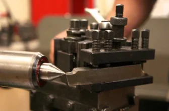
Tool Post: Securely Holding the Cutting Tool
The tool post is mounted on the compound rest and securely holds the cutting tool in place. It allows for quick adjustment of the tool’s height and position. Modern lathes often use quick-change tool posts, which enable rapid swapping of different tools without the need for significant readjustment.
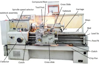
Visual Aid: Importance of an annotated “Lathe machine diagram and basic structure”
A clear understanding of these parts is best achieved with a visual reference. An annotated diagram would typically show:
- The Bed as the foundational structure with guiding ways.
- The Headstock at one end, housing the Spindle and controls for rotation.
- The Tailstock at the other end, capable of supporting the workpiece or holding tools.
- The Carriage assembly (Saddle, Cross-slide, Compound Rest) positioned on the ways, ready to guide the Tool Post and cutting tool.
- The Lead Screw and Feed Rod running parallel to the bed.
- A Chuck mounted on the spindle nose, holding a workpiece.
Such a diagram would visually demonstrate the functional relationship between all these components, making the operation of the lathe much clearer.
The Turning Process: How a Lathe Machine Works
The operation of a lathe machine involves a sequence of precise movements and adjustments. Understanding the working principle is key to operating it effectively and safely.
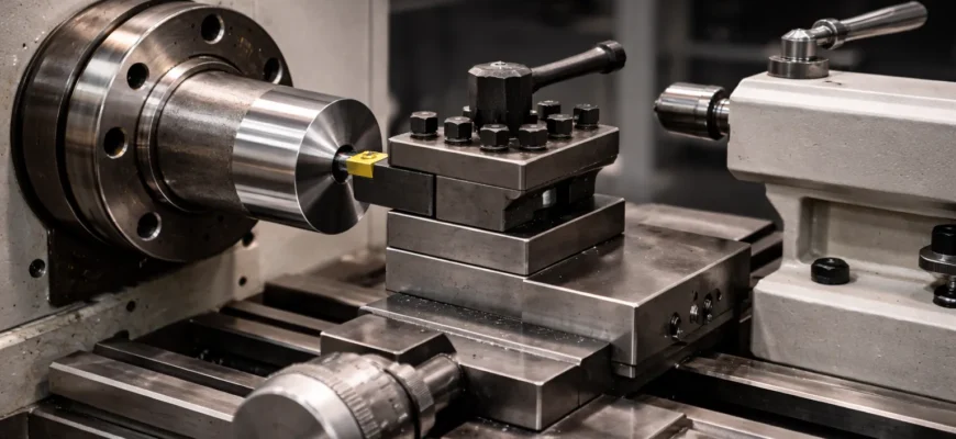
The Fundamental Principle: Relative Motion for Material Removal
The core of the turning process relies on the relative motion between the rotating workpiece and the cutting tool. The workpiece is driven by the headstock’s spindle, and the cutting tool is manipulated by the carriage assembly. Material is removed in the form of chips as the tool’s sharp edge penetrates the surface of the rotating workpiece. The condition for successful machining is that the cutting tool must be harder than the workpiece material and have the correct geometry and sharpness. The relationship between the cutting speed (how fast the surface of the workpiece moves past the tool), the feed rate (how fast the tool moves along or across the workpiece), and the depth of cut (how much material is removed with each pass) are the primary parameters that dictate the efficiency, surface finish, and tool life.
Step-by-Step Working Principle: From Setup to Machining
- Workpiece Setup: The workpiece is securely clamped in the chuck or between centers (one in the headstock spindle, one supported by the tailstock). The workpiece must be centered accurately to avoid vibration and ensure uniform material removal.
- Tool Selection and Mounting: A suitable cutting tool, chosen based on the material and the operation to be performed, is inserted into the tool post and tightened. The tool’s cutting edge is set to the correct height, typically aligned with the center of the workpiece.
- Setting Spindle Speed: The appropriate spindle speed is selected using the gearbox, considering the material’s machinability, the tool’s cutting speed capabilities, and the diameter of the workpiece. Numbers representing RPM are critical here; for example, softer metals might require higher speeds than harder steels.
- Engaging the Feed: The carriage is moved to bring the cutting tool into contact with the workpiece.
- Facing: The cross-slide is used to move the tool radially from the center outwards, creating a flat face.
- Turning: The saddle is used to move the tool longitudinally along the workpiece, reducing its diameter.
- Material Removal: As the tool moves, it shaves off material, creating chips. The depth of cut is controlled by the cross-slide and longitudinal feed controls. Multiple passes may be required to achieve the final dimensions.
- Threading: For thread cutting, the lead screw is engaged, and the carriage is precisely synchronized with the spindle’s rotation.
- Tailstock Operations: If drilling or reaming, the tailstock is locked in position, and the drill bit mounted in its quill is advanced into the rotating workpiece.
- Finishing: After roughing passes, finer feeds and shallower depths of cut are used to achieve the desired surface finish and final dimensions.
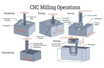
Common Lathe Operations Explained: (“examples” of specific machining tasks)
Lathes are capable of a variety of operations, each requiring specific tool setups and machine movements. Here are some fundamental examples:
- Turning: This is the most basic operation, where the tool moves parallel to the workpiece’s axis of rotation to reduce its diameter. This creates cylindrical parts like shafts.
- Facing: Performed using the cross-slide, facing moves the tool radially across the end of the workpiece to create a flat surface. This is often done to set the length of a part accurately.
- Taper Turning: Achieved by swiveling the compound rest to an angle and then feeding the tool along the angled path, or by offsetting the tailstock. This creates conical shapes.
- Threading: Cutting external or internal screw threads using a specialized threading tool and engaging the lead screw for precise feed.
- Knurling: Creating a textured pattern on the workpiece surface by pressing a knurling tool, which has raised teeth, into the material. This improves grip.
- Drilling: Creating a hole along the axis of rotation by mounting a drill bit in the tailstock and advancing it into the spinning workpiece.
- Boring: Enlarging an existing hole in the workpiece, typically using a boring bar.
- Parting Off (or Cutting Off): Using a narrow tool to cut a finished part from the remaining stock.
Understanding Chip Formation and the Role of Coolants
When a cutting tool removes material, it forms chips. The shape, size, and temperature of these chips provide valuable information about the machining process. Efficient chip formation results in smaller, more manageable chips that break away cleanly. Inefficient cutting can lead to long, stringy chips that can wrap around the workpiece or tool, causing damage or poor finishes.
Coolants, or cutting fluids, play a vital role in lathe operations. They serve multiple purposes:
- Cooling: They dissipate heat generated by the friction between the tool and the workpiece, preventing overheating of both. Managing temperature is crucial for tool longevity and material integrity.
- Lubrication: They reduce friction, allowing for smoother cutting and a better surface finish.
- Chip Flushing: They help wash away chips from the cutting zone, preventing them from interfering with the cut.
- Corrosion Prevention: Some coolants contain additives to protect the workpiece and machine from rust.
The choice of coolant and its application method (flood, mist, or soluble oil) depend on the workpiece material, the type of operation, and environmental considerations.
Varieties of Lathe Machines: Matching the Machine to the Task
Lathes are not one-size-fits-all tools; they come in various types, each designed for specific applications and production volumes. Understanding these differences helps in selecting the right machine for a particular job.
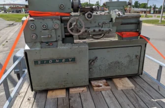
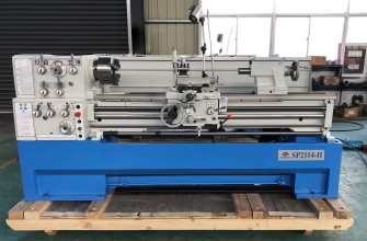
Engine Lathes: The Versatile Workhorse for General Machining
The engine lathe is perhaps the most common type of lathe and is often considered the standard for general-purpose machining. It is characterized by its versatility and ability to perform a wide range of operations, including turning, facing, threading, and tapering. It is typically controlled manually by the operator, who uses handwheels and levers to move the carriage and adjust speeds. Engine lathes come in various sizes, from small benchtop models suitable for hobbyists to large industrial machines capable of handling substantial workpieces. The relationship between the operator’s skill and the machine’s capabilities defines the outcome.
Turret Lathes: Designed for Repetitive Production and Multiple Operations
Turret lathes are designed for high-volume production of identical parts. Instead of a single tool post, they feature a turret, which is a rotating head that can hold multiple cutting tools. This allows the operator to quickly index the turret to bring a different tool into position without stopping the machine, significantly reducing cycle times. Some turret lathes are manually operated, while others are semi-automatic or fully automatic. They are highly efficient for repetitive tasks such as turning, drilling, and tapping on a large scale. The numbers of parts produced per hour on a turret lathe far exceed those on a standard engine lathe for repetitive tasks.
Tool Room Lathes: Precision for Intricate Work
Tool room lathes are built for extreme precision and accuracy. They are typically more robustly constructed and have finer controls than engine lathes, allowing for very precise adjustments. These machines are used for creating precision tooling, dies, molds, and prototypes where exacting tolerances and superior surface finishes are paramount. They often feature specialized measuring devices and higher gear ratios for very fine feeds. The clarity of design and manufacturing in a tool room lathe allows for operations that demand tolerances measured in microns.
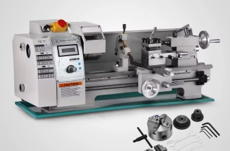
Bench Lathes: Compact Power for Smaller Tasks
Bench lathes are smaller, compact versions of engine lathes designed to be mounted on a workbench. They are ideal for small workshops, educational institutions, and for working on smaller, intricate parts. Despite their size, they can perform many of the same operations as larger lathes, albeit with limitations on workpiece size and material removal capacity.
Automatic and CNC Lathes: The Future of Manufacturing
As mentioned earlier, automatic and CNC (Computer Numerical Control) lathes represent the advanced end of lathe technology. These machines are programmed via computers to perform complex machining sequences with minimal human intervention. They offer unparalleled precision, repeatability, and efficiency, making them the backbone of modern manufacturing. The industrial automation market is projected to reach $378.57 billion by 2030, growing at a 10.8% CAGR from $206.33 billion in 2024 Insights from Industry, 2025, a trend heavily driven by sophisticated CNC machinery like lathes. The difference between manual and automatic lathe machine operations is stark in terms of speed, consistency, and complexity achievable.
Essential Uses and Applications of Lathes
The lathe’s ability to create precise, symmetrical parts makes it indispensable across a vast array of industries and applications. Its utility spans from heavy manufacturing to delicate craftwork.
Manufacturing and Engineering: The Backbone of Production
In general manufacturing and engineering, lathes are fundamental for producing a wide array of components. This includes creating shafts, gears, bolts, nuts, couplings, and housings that are essential for assembling machinery, vehicles, and countless industrial equipment. The precision afforded by lathes ensures that these parts mate correctly, contributing to the overall reliability and performance of the final product. The automotive machining market’s growth highlights the continued reliance on these tools for mass production.
Aerospace Industry: Precision at Critical Tolerances
The aerospace sector demands the highest levels of precision and reliability. Lathes are used to manufacture critical components such as engine shafts, turbine blades, landing gear parts, and fuselage sections. Materials used in aerospace, like titanium and high-strength alloys, often require specialized machining techniques that lathes can provide. The aircraft machine tools market was valued at USD 3.5 billion in 2024 and is projected to reach USD 4.9 billion by 2032 Stratview Research, 2026, illustrating the significant demand for precise machinery in this field.
Automotive Industry: From Engine Parts to Chassis Components
As mentioned, the automotive industry is a major consumer of lathe-machined parts. Engines, transmissions, drivetrains, brake systems, and steering components all rely on precisely turned parts. The ability of lathes to efficiently produce large volumes of identical, high-quality components makes them ideal for the demands of automotive manufacturing.
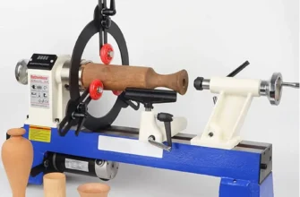
Woodworking and Furniture Making: Crafting Elegance
In woodworking, lathes are used to create turned components such as table legs, chair spindles, bedposts, bowls, and decorative turnings. Woodturning offers a unique aesthetic and functional capability that is hard to replicate with other methods. The relationship between the wood’s grain, the cutting tool, and the operator’s skill is crucial for achieving beautiful results.
Prototyping and Research: Bringing Ideas to Life
For engineers and designers, lathes are invaluable for creating prototypes and experimental components. They allow for rapid iteration and modification of designs, enabling quick testing and refinement of new products. The ability to machine various materials, including plastics and metals, makes them versatile tools for R&D.
Hobbyist and DIY Applications: Empowering Creativity
Beyond industrial applications, hobbyists and DIY enthusiasts utilize lathes for a wide range of projects, from crafting custom tools and parts to creating artistic pieces. Bench lathes and smaller engine lathes make these capabilities accessible for personal workshops.
Lathe Machine Specifications: Understanding Performance Metrics
When selecting or operating a lathe, understanding its specifications is crucial. These numbers and parameters define the machine’s capabilities and suitability for specific tasks.
Swing: The Maximum Workpiece Diameter
The “swing” of a lathe refers to the maximum diameter of a workpiece that can be rotated over the bed. It is typically specified as the distance from the spindle centerline to the bed’s ways, multiplied by two. A larger swing indicates the machine’s capacity to handle wider workpieces.
Distance Between Centers: The Maximum Workpiece Length
This specification indicates the maximum length of a workpiece that can be mounted between the centers of the headstock and tailstock. It defines the machine’s capacity for long parts.
Spindle Speed Range: RPM Variations
The spindle speed, measured in revolutions per minute (RPM), determines how fast the workpiece rotates. Lathes have a range of speeds, either selectable through gears or variable frequency drives (VFDs). A wider speed range allows for more versatility in machining different materials and performing various operations. For example, high speeds are good for finishing softer materials, while lower speeds are better for tough materials or heavy cuts.
Horsepower (HP): Power and Capability
The horsepower of the lathe’s motor indicates its power output. Higher horsepower generally means the machine can handle heavier cuts, larger workpieces, and more demanding materials without bogging down. The relationship between motor horsepower and cutting force is a key indicator of capability.
Tailstock Taper: Tooling Compatibility
The tailstock has a tapered bore (e.g., Morse taper) designed to accept standard tooling like centers, drill chucks, and collet chucks. The size of the taper (e.g., MT #2, MT #3) determines the size and type of tooling that can be used.
Bed Construction and Ways: Precision and Durability
The material and construction of the bed, along with the precision of the ways, are critical for accuracy and longevity. Hardened and ground ways offer better durability and maintain precision over time compared to unhardened or less precisely machined ways.
Accessories and Enhancements: Expanding Lathe Capabilities
Various accessories can significantly enhance the functionality and versatility of a lathe machine, allowing it to perform a wider range of tasks and improve efficiency.
Steady Rests and Follow Rests: Supporting Long Workpieces
For long, slender workpieces that might sag or vibrate excessively when supported only at the ends, steady rests and follow rests provide crucial support. A steady rest is anchored to the lathe bed and supports the rotating workpiece at a single point, while a follow rest is attached to the carriage and follows the tool, providing support right at the point of cutting.
Live Centers and Revolving Centers: Reducing Friction
While a standard dead center in the tailstock rotates with the workpiece, a live center is mounted on its own bearings and remains stationary relative to the workpiece, reducing friction and heat buildup, especially during extended operations.
Lathe Dogs and Mandrels: Workpiece Mounting
Lathe dogs are used in conjunction with a faceplate or chuck to transmit rotational drive to a workpiece mounted between centers. Mandrels are specialized shafts used to hold workpieces that have a precisely bored hole, ensuring concentricity.
Turrets and Tooling Systems: For Production Efficiency
As mentioned in the types of lathes, turret systems allow for the rapid indexing and use of multiple tools, dramatically increasing production rates for repetitive tasks.
DROs (Digital Readouts) and Power Feeds: Enhancing Precision and Ease of Use
Digital Readouts provide precise, digital readouts of the carriage and cross-slide positions, greatly improving accuracy for manual operations. Power feeds, which are standard on many engine lathes and automated on CNC machines, provide controlled and consistent movement of the carriage and cross-slide, reducing operator fatigue and improving finish consistency.
Safety First: Operating a Lathe Responsibly
Lathes are powerful machines that, when operated incorrectly, can pose significant safety risks. Adhering to strict safety protocols is paramount.
Personal Protective Equipment (PPE): The First Line of Defense
- Safety Glasses: Always wear safety glasses or a face shield to protect your eyes from flying chips and debris.
- Appropriate Clothing: Avoid loose clothing, dangling jewelry, or long hair that could get caught in the rotating machinery. Wear sturdy, closed-toe shoes.
- Gloves: Generally, avoid wearing gloves when operating a lathe, as they can get caught. However, for specific material handling tasks, appropriate cut-resistant gloves might be necessary, used with extreme caution.
Machine Operation Safety:
- Secure Workpiece: Ensure the workpiece is securely clamped in the chuck or between centers. A loose workpiece can be violently ejected from the machine.
- Clear Workspace: Keep the area around the lathe clean and free of clutter. Remove wrenches and tools from the chuck or spindle before starting the machine.
- Tooling Check: Ensure the cutting tool is sharp, properly mounted, and securely locked in the tool post.
- Guard Engagement: Use all machine guards and safety features provided.
- Never Reach: Never reach over or under a running machine to adjust something. Stop the machine if you need to make adjustments.
- Slow and Steady: Begin operations at slow speeds to check for clearance and stability before increasing to the desired cutting speed.
- Chip Management: Use a brush or hook to remove chips; never use your hands while the machine is running.
- Coolant Management: Be aware of the coolant’s temperature and flow to ensure effective cooling and lubrication.
Emergency Procedures: Knowing What to Do
Familiarize yourself with the location of the emergency stop button and understand how to shut down the machine quickly in case of an accident or unexpected event.
What’s Next?
You have now journeyed through the definition, historical evolution, intricate parts, fundamental working principles, diverse varieties, and essential uses of the lathe machine. You’ve learned how specifications define its capabilities and how accessories can expand its utility, all while understanding the critical importance of safety.
By understanding the relationship between the various components and the mechanics of material removal, you have gained a solid grasp of this foundational manufacturing tool. You’ve seen examples of its application across industries, from the precision required in aerospace to the elegance of woodworking. You’ve also seen how the integration of computers has propelled lathes into the realm of high-precision automation, making the difference between manual and automatic lathe machine operations a key consideration in modern manufacturing. The ability to achieve exact dimensions and smooth finishes, coupled with the machine’s versatility, ensures its continued relevance.
Your next steps can involve:
- Practical Application: If you have access to a lathe, begin with simple operations on soft materials like wood or aluminum. Practice turning, facing, and drilling. Remember to start slow and always prioritize safety.
- Further Learning: Explore more advanced lathe operations such as threading, taper turning, and parting off. Research different types of cutting tools and their geometries for various materials.
- Understanding Materials: Learn about the machinability of different metals and plastics and how their properties (hardness, ductility) affect cutting parameters like speed, feed, and depth of cut.
- Investigate CNC: If you are interested in modern manufacturing, delve deeper into CNC programming and operation. Understanding manual lathes provides a strong conceptual foundation for grasping CNC principles.
- Explore Related Tools: Consider learning about other complementary machine tools like milling machines, grinders, and band saws to gain a broader understanding of subtractive manufacturing processes.
The world of machining is vast and rewarding. Your journey into understanding the lathe machine is a crucial first step. Keep exploring, keep practicing, and keep prioritizing safety, and you’ll find yourself capable of shaping materials with precision and confidence.