
Lathe tooling is not simply a collection of cutting edges — it is a complete mechanical system in which the cutting insert, tool holder, tool post, workholding, and machine rigidity interact to determine whether you produce a good part or chase problems for an entire shift. A premium carbide insert in a poor holder, set off-center, on a loose machine will outperform nothing. Understanding the full tooling system — not just the cutting tool — is what separates consistently accurate lathe work from frustrating, inconsistent results.
Quick answers:
What Is Lathe Tooling?
“Lathe tooling” is an umbrella term that covers the entire cutting system mounted on the carriage, not just the piece of carbide or HSS doing the actual cutting.
The complete tooling system includes:
- The cutting tool or insert — the geometry that actually contacts the workpiece and removes material. This may be a solid HSS tool bit, an indexable carbide insert in a holder, or a brazed carbide tip.
- The tool holder — the steel body that clamps the insert or tool bit and provides the mounting interface to the tool post. Holder rigidity, overhang, and shank size directly affect vibration and dimensional stability.
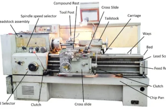
- The tool post — the device bolted to the compound rest that receives and locks tool holders. The tool post type — rocker, four-way indexing, or quick-change — determines how quickly and repeatably tools can be changed and set to center height.
- Setup hardware — shims, center-height gauges, tool height gauges, torx keys for indexable inserts, and clamping hardware that ensure correct tool geometry before the spindle starts.
The critical insight is this: tooling is a chain, and the weakest link determines the result. You cannot correct a poor holder with a better insert, or a bad tool post with a better holder. Every link must be adequate for the work being done.
Main Types of Lathe Cutting Tools
Turning Tools
Turning tools reduce the outer diameter of the workpiece — the most fundamental lathe operation. They are characterized by their approach angle (how the tool enters the workpiece) and nose radius (the corner radius at the cutting point).
Key distinctions:
- Roughing turning tools use a larger nose radius, negative rake where possible, and are designed for maximum material removal rate (MRR) with high depth of cut and feed. The priority is stock removal, not finish.
- Finishing turning tools use a smaller nose radius and finer feed, producing lower Ra surface finish and closer dimensional control. The priority is precision and finish over removal rate.
- Profiling/contour tools (often DCMT or VCMT inserts) have a sharper, more acute nose angle allowing the tool to reach into shoulders, tapers, and contoured profiles that a standard CNMG holder cannot access.
When used: Any time the OD of a part needs to be reduced in diameter, stepped, contoured, or brought to a finished size and surface finish.
Facing Tools
Facing tools produce a flat surface perpendicular to the spindle axis at the end of the workpiece. In practice, many turning tool holders — particularly 93° and 95° approach angle holders — are capable of both turning and facing from the same setup by feeding the cross slide radially inward.
Dedicated facing tools are right-hand or left-hand geometry holders optimized for the radial feed direction, providing better chip flow and clearance on facing operations.
When used: To square bar ends, set part length, create reference surfaces, and face shoulders between diameters.
Boring Tools (Boring Bars)
Boring bars are internal turning tools — a cutting insert or solid HSS tip mounted on a round or square shank that enters the bore of the workpiece. They enlarge, straighten, and finish existing holes to precise diameter, location, and surface finish that drilling alone cannot achieve.
Key practical points:
- Maximum shank diameter should be as large as the bore will allow — larger shank = more rigidity = less chatter and better finish.
- Minimum overhang — keep the boring bar as short as the bore depth requires. Standard guidance: limit overhang to 4× the bar diameter for steel bars; anti-vibration bars extend this to 6–10× for deep bores.
- Insert selection for boring leans toward positive rake geometry to reduce the radial cutting force that tends to push a boring bar away from the cut.
When used: For bearing housings, hydraulic cylinder bores, any internal feature requiring tolerance tighter than a drill can hold, and finishing bored holes to IT6–IT7 tolerance.
Threading Tools
Threading tools cut external or internal helical grooves to create threads for fasteners, couplings, or pipe connections. On manual lathes, single-point threading tools with a 60° (metric/unified) or 55° (BSP/Whitworth) included angle ground on HSS or using a laydown threading insert are standard.
Single-point threading inserts (laydown type — ISO/UN/ACME profiles) index on wear and are the standard for production CNC threading. Full-profile inserts cut the thread root and flanks in one pass for clean thread form; partial-profile inserts are grade-specific and require matching to the pitch being cut.
When used: Any application requiring custom thread pitch, non-standard thread forms, fine-pitch threads unavailable in standard tap/die sets, or high-volume threading in CNC production.
Grooving Tools
Grooving tools cut controlled-width channels (grooves) into the OD, face, or bore of a workpiece using a form insert with a defined width. Standard applications include:
- O-ring grooves (specific width and depth tolerances for seal function)
- Retaining ring grooves (standardized per DIN/ANSI snap ring standards)
- Undercuts before threading (provides a run-out zone for the threading tool)
- Oil grooves in bearing journals
- Face grooves in flanges
Grooving and parting differ in depth: grooving cuts to a controlled depth and stops; parting cuts all the way through.
Form Tools
Form tools are custom-ground HSS or custom-configured insert tools with a specific profile that replicates a complex shape in a single plunge cut. Common in high-volume production of knobs, radiused profiles, and specific recesses where the form appears on every part. The advantage is cycle time — one plunge replaces multiple passes. The disadvantage is that each form tool is dedicated to one geometry.
HSS vs. Carbide Inserts
This is the most consequential tooling decision for manual lathe users and beginners — and it is not as straightforward as “carbide is always better.”
High-Speed Steel (HSS)
HSS is a high-alloy tool steel (typically M2 or T15 grade) that can be ground and resharpened to any geometry by the machinist. It is tough, shock-resistant, and forgiving of interrupted cuts, setup errors, and variable conditions.
HSS characteristics:
- Maximum cutting speed: 20–40 m/min on steel (slow by modern standards)
- Toughness: Excellent — handles interrupted cuts, variable chip loads, and thin walls well
- Sharpening: Fully resharpable on a bench grinder with suitable wheels — allows custom geometries
- Cost per tool: Very low — a set of HSS blanks costs a fraction of indexed carbide systems
- Center height adjustment: Easy — the tool is physically ground until it reaches center
- Beginner-friendliness: High for tool geometry experimentation; lower for speed/feed optimization
Best for: Hobby and educational lathes with modest spindle power and rigidity, non-ferrous metals (aluminum, brass, copper) where high rake angles improve finish, interrupted cuts, thin-wall parts, and situations where a custom geometry is needed quickly.
Carbide Inserts
Carbide inserts are precision-pressed and sintered tungsten carbide cutting edges in standardized geometries, typically coated with TiN, TiAlN, AlCrN, or CVD multi-layer coatings. They are indexed when worn — rotated to a fresh edge — rather than resharpened.
Carbide insert characteristics:
- Maximum cutting speed: 100–400 m/min on steel (4–10× faster than HSS)
- Hardness: Much harder than HSS — far better wear resistance at elevated temperatures
- Toughness: Lower than HSS — more sensitive to interrupted cuts and vibration, particularly with ceramic-type grades
- Sharpening: Not resharpened — indexed when worn. Edge quality is consistent and repeatable
- Cost system: Higher initial holder cost, ongoing insert cost — but lower cost per cutting edge in production
- Machine requirement: Carbide inserts need adequate spindle power and machine rigidity to run at the speeds and feeds where they perform correctly. On a small, light lathe, carbide often performs worse than HSS because the machine cannot provide the cutting conditions carbide requires
The honest comparison
The practical rule: If your lathe is a small to medium hobby or toolroom machine with modest power (under 1 HP), HSS will often outperform carbide inserts because the machine cannot provide the rigidity and power that carbide needs to cut cleanly. If your machine is a production-grade manual lathe or CNC turning center with good rigidity and adequate power, carbide inserts are almost always the right choice for steel and stainless work.
Carbide insert grades and identification
Carbide inserts follow the ISO designation system — for example, CNMG 432 breaks down as:
- C = 80° rhombic shape
- N = 0° clearance angle (negative rake)
- M = M tolerance class
- G = specific chipbreaker/geometry
- 4 = 12.7 mm inscribed circle (IC)
- 3 = 3/16″ thickness
- 2 = 0.031″ nose radius
For turning steel: CNMG (roughing) and TNMG or DCMT (finishing/profiling) are the most common geometries. For aluminum: CCGT with sharp, positive rake geometry and bright (uncoated) finish. For stainless: M-grade carbide with PVD coating and positive geometry to minimize work-hardening.
Parting Tools Explained
If there is one area of lathe tooling where setup, geometry, and rigidity matter more than anywhere else, it is parting. More lathe tooling failures — broken tools, destroyed workpieces, wrecked setups — happen during parting than in any other operation.
What parting tools do
Parting tools (also called cut-off tools) use a narrow blade or insert to cut completely through the rotating workpiece, separating the finished part from the bar stock. The cut is made at the full radius of the workpiece in a plunging motion — radially inward from OD to zero.
This geometry creates a unique set of challenges:
- As the blade cuts deeper, blade overhang relative to the supported section increases — the unsupported cutting length grows as the work progresses
- The chip must escape from a progressively deepening, narrow slot
- The full width of the insert contacts material simultaneously — unlike turning where only a small portion of the cutting edge is engaged at any time
- Any deflection, chatter, or tool movement causes the blade to bind in the slot — which jams the cut and usually breaks the insert or blade
Why parting is the most failure-prone lathe operation
Three factors make parting uniquely demanding:
- Blade geometry forces deflection under load. A parting blade is thin and tall — it has a high aspect ratio that makes it act like a spring under the lateral forces of cutting. Any looseness in the setup amplifies this deflection into chatter and dig-in.
- Chip evacuation is constrained. The chip must travel out of a slot that is exactly as wide as the blade — there is no lateral relief. Poor chip formation or curling causes chip jamming, which loads the blade and breaks it.
- The cut cannot be reversed or recovered easily. Unlike a turning pass where you can ease the tool back and re-approach, a parting cut that grabs or chatters typically results in tool breakage if not immediately addressed.
How parting tools differ from turning tools
Blade width selection
Parting blade width is a trade-off between rigidity and material waste (kerf):
- 2 mm (0.079″): Minimum kerf, lowest cutting force — but also minimum stiffness. Suitable for small-diameter work (under ~40 mm) on light machines.
- 3 mm (0.118″): The most common general-purpose parting width. Good balance of rigidity and kerf for medium-diameter work.
- 4 mm (0.157″): Higher rigidity — better for larger diameters and production work, at the cost of higher cutting force and wider kerf.
HSS parting blades vs. indexable carbide parting tools
HSS parting blades: Narrow HSS blades ground with front rake and relief. Cheap, resharpable, and tolerant of the marginal conditions on smaller machines. The cutting geometry can be customized — adding positive rake improves chip flow significantly on difficult materials.
Indexable carbide parting tools: Use precision-ground carbide inserts in a rigid blade holder. Higher cutting speed capability, consistent insert geometry, and excellent chip-breaking profiles. Require more machine rigidity and power to work correctly — on a light or worn lathe, a carbide parting insert can perform worse than a sharp HSS blade because the machine cannot provide the rigidity the carbide system demands.
Practical recommendation: On hobby and light manual lathes, a sharp HSS parting blade in a rear-mounted tool post (which eliminates the dig-in tendency) or a front-mounted holder with maximum clamping rigidity works well. On production manual lathes and CNC lathes with good rigidity, indexable carbide parting tools deliver consistent performance and repeatability.
Parting tool setup: the non-negotiables
- Dead on center height — a parting tool even 0.1 mm above center on a 30 mm diameter part creates a geometry error that dramatically increases the tendency to grab. Set it exactly on center, every time.
- Perpendicular to the spindle axis — any angular misalignment causes the blade to cut into one side of the slot, increasing lateral loading and deflection.
- Minimum overhang — extend the blade only as far as required for the workpiece radius plus 2–3 mm clearance. Every extra millimeter of overhang is a multiplier of deflection under load.
- Maximum clamping rigidity — tighten every clamping bolt. Check that the tool post is fully locked and the holder is fully seated.
- Adequate cutting fluid — flooding the parting slot with cutting fluid (sulfurized cutting oil for steel, WD-40 or kerosene for aluminum) lubricates the chip and dramatically reduces the tendency to grab.
Tool Holders, Tool Posts, and Quick-Change Systems
What holders do — and why rigidity is the priority
A tool holder does two things: it positions the cutting insert at the correct geometry and center height, and it rigidly supports the insert against the three-dimensional cutting forces that the lathe generates. When a holder flexes or vibrates under cutting load, the cutting geometry changes dynamically — producing chatter, dimensional variation, poor finish, and accelerated insert wear.
The rules for holder selection are simple:
- Use the largest shank size your tool post and machine will accommodate. A 25 mm shank holder on a machine with 20 mm capacity will not fit. But using a 16 mm shank on a machine that accepts 25 mm means you are leaving rigidity on the table.
- Keep overhang minimal. Every millimeter of overhang beyond the minimum required reduces rigidity. The standard guidance is: holder shank overhang beyond the tool post should not exceed 1.5× the shank height for steel holders.
- Ensure the holder is fully seated. A holder partially inserted into the tool post, or a tool post base not fully clamped to the compound, undermines every other rigidity measure you have taken.
Rocker-type tool post (standard single-tool post)
The original manual lathe tool post — a slotted ring and rocker that accepts a single tool bit. Adjustable for center height by shimming or rocking the rocker.
Pros: Simple, cheap, no moving parts.
Cons: Slow to change tools, inconsistent center height on every tool change, poor repeatability, single tool capacity.
Verdict: Adequate for learning. Not suitable for a working shop or even serious hobby use.
Four-way indexing tool post
A square turret that holds four pre-mounted tools and rotates to index to each. Each position must be individually set to center height — but once set, you can return to it quickly.
Pros: Four tools ready, faster than rocker, cheap.
Cons: Center height setting is not independently adjustable per position — shimming is required. Limited by the height of the holders to center relationship. Repeats center height inconsistently when indexed back.
Quick-Change Tool Post (QCTP)
The quick-change tool post (QCTP) system — Aloris, Dorian, Dickson/Multifix, and equivalent import systems — is the most significant practical upgrade for any manual lathe, and the standard for toolroom and production manual work.
A QCTP consists of a base bolted to the compound rest and individual tool holders that lock onto the base via a dovetail and locking cam or bolt. Each holder has an independent height adjustment (a screw and wedge or similar mechanism) that sets that holder’s center height precisely and repeatably.
The key advantage: When you swap a tool holder on a QCTP, the new holder returns to its pre-set center height within a few hundredths of a millimeter. You set each holder’s center height once, mark the position, and every subsequent swap is immediate and accurate — without shimming, re-indicating, or re-setting.
QCTP holder types:
- Standard turning/boring holder (most common — accepts square shank tool bits)
- Boring bar holder (accepts round boring bars)
- Parting blade holder (narrow, rigid blade clamp)
- Threading holder (45° angle, accepts threading tools)
- Knurling tool holder
- Live center / drill chuck holder
Sizing: QCTP systems are sized to the lathe’s center height. Common sizes: AXA (small lathes, up to ~10″ swing), BXA (medium lathes, 12–15″ swing), CXA (larger lathes, 15–18″ swing). Matching the system size to the machine ensures holders are at correct center height without excessive shimming.
How to Set Up Lathe Tooling Correctly
Most lathe tooling problems are actually setup problems. Before assuming the insert grade is wrong or the holder is defective, check the setup against every item below.
Center height — the single most critical setup parameter
The cutting tool tip must be exactly at the spindle centerline. The consequences of incorrect center height:
- Tool tip above center: The effective clearance angle decreases, the tool rubs on the workpiece rather than cutting cleanly, cutting forces increase, and a small taper appears on the workpiece. On parting operations, above-center tools are the primary cause of grab and breakage.
- Tool tip below center: The effective rake angle changes unfavorably, cutting pressure increases, surface finish degrades, and on parting operations, below-center positioning causes the same grab tendency as above-center.
How to set center height:
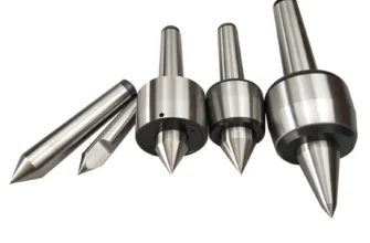
- Bring a Morse taper dead center in the tailstock to the headstock spindle — place the tool tip against the point. Adjust height until there is no gap or overlap.
- Face a small piece of bar stock — if a small pip remains at center when facing to zero, the tool is below center. A feather of metal curling off at center indicates above center.
- Use a center height gauge against the spindle center mark on the headstock for rapid, repeatable setting.
Overhang — keep it as short as the job allows
Overhang is the distance the tool extends beyond the clamping point of the holder. This is the single largest variable in vibration and surface finish on turning operations.
Guidance:
- For turning operations: Limit overhang to 1.5× the tool shank height for standard steel holders
- For boring bars: Limit overhang to 4× bar diameter for standard bars; up to 6–10× for anti-vibration bars
- For parting blades: Minimum overhang beyond the holder that clears the workpiece radius — and no more
Tool orientation — square and parallel
The holder must be perpendicular to the spindle axis (or at the intended approach angle) and the cutting tip must be correctly oriented. A turning holder rotated slightly from perpendicular changes the effective lead angle, altering chip direction, surface finish, and the axial force balance on the workpiece.
Holder clamping — fully torqued, no exceptions
Every clamping bolt must be fully and evenly torqued before making a cut. This includes:
- Insert clamp screw torqued to manufacturer specification (typically 2–4 Nm for small inserts)
- Holder clamping bolt fully engaged in the tool post
- Tool post locking nut or cam fully tightened
- Compound rest gibs appropriately adjusted — no rocking under cutting load
Insert alignment — tip at correct orientation
Indexable inserts must be fully seated in the insert pocket — no chips, no debris under the insert, no rocking. A tilted insert changes the cutting geometry and contact area, and can cause premature chipping from uneven load distribution.
Shop Setup: What Makes Lathe Tooling Work Well
The tooling system does not exist in isolation. The broader shop and machine environment determines whether good tooling delivers good results.
Workholding and chuck condition
A chuck with 0.1 mm runout cannot produce a concentric part, regardless of tooling quality. Check chuck jaw condition and runout regularly. For precision work, indicating the workpiece in a 4-jaw independent chuck or collet system eliminates chuck runout as a variable.
Tailstock support for long workpieces
Any shaft or bar with a length-to-diameter (L/D) ratio greater than approximately 4:1 should be supported at the tailstock end with a live center. Without support, radial cutting force deflects the workpiece — producing barrel-shaped diameter variation, chatter, and poor finish that no tooling choice can correct.
For L/D ratios above 8–10:1, a steady rest or follow rest is needed in addition to or instead of tailstock support.
Machine rigidity and bed condition
A worn lathe bed with loose gibs, worn ways, or a twisted bed frame limits the achievable accuracy and surface finish regardless of tooling. Before troubleshooting tooling, check:
- Carriage and cross-slide gib tightness (snug but not binding)
- Headstock bolts fully tightened
- Machine leveled and anchored to prevent bed twist
- Ways clean and oiled
Coolant and lubrication
Cutting fluid does four things: cools the cutting zone, lubricates chip flow, prevents built-up edge, and flushes chips away from the cut. Without adequate coolant:
- Tool life on steel is dramatically reduced
- Built-up edge forms on carbide inserts at low speeds
- Parting operations dry-grab and fail
- Surface finish degrades from thermal effects
For steel on a manual lathe: sulfurized cutting oil (neat cutting oil) is excellent for threading, parting, and finishing passes. Soluble oil coolant (mixed with water) works well for general turning. For aluminum: WD-40, kerosene, or isopropyl alcohol provides the lubrication needed without leaving residue.
Chip control and evacuation
Chips wrapping around the workpiece or chuck are a safety hazard and a surface quality problem — re-cut chips pressed against the workpiece by the cutting tool will score the surface. Use chipbreaker insert geometries matched to the material and feed rate, apply coolant to direct chips away from the cut, and clear chip nests regularly with a hook tool (never by hand near a rotating chuck).
Common Lathe Tooling Problems and How to Fix Them
This section addresses the problems that machinists actually encounter — not theoretical failure modes.
Chatter
What it looks like: Vibration marks on the workpiece surface — regular ripple patterns, often with an audible rattle or squeal during cutting.
Common causes and fixes:
Tool Breakage (Insert Chipping)
Common causes:
- Interrupted cut (key-seat, holes, welded workpiece) with a grade not suited for impact
- Depth of cut too aggressive on the first pass into hard scale or interrupted surfaces
- Insert seated incorrectly — rocking in pocket
- Parting blade grabbing due to off-center height or insufficient rigidity
Fixes: Use a tougher insert grade (more cobalt binder, CVD coating) for interrupted work. Pre-chamfer the scale or use a dedicated scale-breaking pass. Check insert seating. On parting, return to setup fundamentals — center height, overhang, clamping.
Poor Surface Finish
Common causes and fixes:
Parting Tool Grabbing
The most feared and most preventable lathe failure mode.
Causes:
- Tool not exactly on center height
- Insufficient blade clamping rigidity
- No cutting fluid in the slot
- Blade overhang too long
- Spindle speed too slow (insufficient chip velocity to evacuate the slot)
Fixes: Reset center height precisely. Reduce overhang to minimum. Flood with cutting fluid. Increase spindle speed slightly. If on a small machine, try rear-mounted parting tooling which largely eliminates the grab tendency by loading the tool in tension rather than compression.
Built-Up Edge (BUE)
What it is: A deposit of work material that welds onto the cutting edge, forming a false cutting edge that produces poor finish and inconsistent dimension — common in soft steel and aluminum at low cutting speeds.
Fix: Increase cutting speed (carbide requires minimum cutting speed to stay hot enough at the tip to prevent adhesion). Use coated inserts (TiAlN coating reduces adhesion). Use cutting fluid. For aluminum, switch to uncoated or PVD-coated sharp positive-rake inserts.
Wandering or Taper on Turned Diameter
Causes:
- Tailstock misaligned (for work-between-centers)
- Bed twist (for long workpieces)
- Carriage gibs too loose (inconsistent depth of cut along length)
- Workpiece deflecting under cutting force (insufficient support)
Fix: Verify tailstock alignment by test-turning a bar between centers and measuring both ends. Check and adjust bed leveling. Tighten carriage gibs. Add steady rest or tailstock support for long slender parts.
How to Choose the Right Tooling for Your Lathe
Match tooling to machine capability
Small lathes (under 8″ swing, under 0.75 HP): HSS tools in a QCTP or four-way post. Carbide inserts will underperform on these machines because they need more rigidity and power than the machine provides.
Medium manual lathes (10–14″ swing, 1–3 HP): Carbide inserts start performing well here. Use positive-rake insert geometries (CCMT, DCMT, TCMT) which cut at lower forces — well matched to machines with moderate rigidity. QCTP essential.
Production manual and CNC lathes (16″+ swing, 5+ HP): Full carbide system with standard negative-rake inserts (CNMG, TNMG) for steel, specialized grades for stainless and exotics. Insert grade selection by ISO material group (P, M, K, N, S, H) matched to workpiece material.
Match tooling to work type
- Mixed one-offs and repairs: QCTP system with 4–6 holders covers all operations. HSS for customs, carbide for standard turning.
- Repeat production: Carbide inserts with consistent grade and geometry — documented speed and feed settings for each operation and material.
- Precision toolroom work: Best available QCTP system, precision holders, carbide inserts with tight tolerance grade for finishing.
- CNC turning: Production insert system (CNMG/TNMG roughing, DCMT/VCMT finishing) with qualified holders and through-coolant if available.
Material-specific tooling priorities
Recommended Starter Tooling Setup
For a machinist setting up a medium manual lathe (10–13″ swing) for the first time or re-tooling a shop lathe, here is the practical minimum setup that covers 90% of turning work:
The tool post system
- Quick-change tool post (BXA size for 12–15″ swing) with at minimum 4–6 holders. This is the most important single investment in manual lathe tooling. Aloris, Dorian, or quality import (Phase II, Dorian-style) at minimum.
Cutting tools
- Right-hand turning/facing holder with CNMG 432 inserts for steel roughing. This single holder performs both turning and facing — one holder, two operations.
- DCMT or CCMT holder with positive-rake inserts for finishing passes, aluminum, and profiling work requiring sharper tool geometry.
- Boring bar set — at minimum a 12 mm and 20 mm boring bar with carbide inserts. These cover the majority of boring work on medium lathes.
- Threading tool holder with 60° and 55° laydown threading inserts (metric and imperial profiles).
Parting setup
- Indexable carbide parting tool in a rigid blade holder — either rear-mounted (preferred for chatter elimination) or front-mounted with the most rigid QCTP holder available. Starting width: 3 mm.
- Alternatively, a quality HSS parting blade if the machine is small or the carbide system does not suit the machine’s rigidity.
Measuring and setup tools
- Center height gauge (or use a dead center in tailstock — free)
- Dial test indicator (0.001″ / 0.02 mm resolution minimum) for chuck indicating and workpiece alignment
- Digital calipers (0.01 mm resolution) and a 0–25 mm micrometer for diameter verification
- Threading gauge / fish tail for checking threading tool alignment to the work axis
Consumables
- Cutting oil (neat sulfurized cutting oil) for steel parting and threading
- Soluble oil coolant for general turning
- Replacement inserts in the grades used — always keep at least one fresh index per holder in stock
FAQ: People Also Ask
What tools do you need for a metal lathe?
At minimum: a right-hand turning/facing tool, a boring bar, a parting tool, a threading tool, and a quick-change tool post system with 4–6 holders. These five tool types cover facing, OD turning, internal boring, threading, and part cut-off — the complete range of fundamental lathe operations. Add grooving, knurling, and form tools as specific jobs require.
What is the difference between HSS and carbide inserts?
HSS is a tough, resharpable tool steel best suited for low cutting speeds, light machines, interrupted cuts, and custom geometries. Carbide inserts are much harder and wear-resistant, enabling high cutting speeds and consistent edge geometry, but require adequate machine power and rigidity to perform correctly. On small hobby lathes, HSS often outperforms carbide. On medium to large production lathes, carbide inserts are almost always the correct choice for steel and stainless work.
What are parting tools used for?
Parting tools cut completely through a rotating workpiece to separate the finished part from bar stock, or cut deep grooves and undercuts. They are the narrowest, most rigidity-sensitive tools in the lathe kit — prone to chatter and insert breakage if setup is incorrect. The most critical setup rules: exactly on center height, minimum blade overhang, maximum clamping rigidity, and adequate cutting fluid in the slot.
Why does my parting tool chatter?
Parting tool chatter is almost always caused by one or more of: tool tip not exactly on center height, blade overhang too long, insufficient rigidity in the clamping setup, no cutting fluid in the slot, or the machine itself lacking sufficient rigidity for the blade and insert system being used. Systematic setup correction — not tool replacement — solves most parting chatter problems.
How do you set a lathe cutting tool correctly?
Set the tool tip exactly on the spindle centerline (verify against a dead center or by facing test). Minimize overhang beyond the holder to the minimum needed for the operation. Ensure the holder is perpendicular to the spindle axis. Torque all clamping hardware fully before cutting. Check that the insert is fully seated with no debris under it, and that the tool post is completely locked.
What is the best tool holder for a lathe?
For any working or serious hobby manual lathe, a quick-change tool post (QCTP) system — Aloris, Dorian, or equivalent quality import — is the most practical and highest-value holder system. The independent center-height adjustment per holder, rapid tool swap capability, and consistent repeatability make it vastly superior to rocker or four-way tool posts for anyone doing regular lathe work.
Do beginners need carbide inserts or HSS?
For a first lathe, HSS is often the better starting point: it is cheap, teaches tool geometry through grinding, is tolerant of marginal conditions, and works well on small machines with modest power. As skill and machine capability develop, transitioning to a QCTP with carbide inserts delivers better performance, faster tool changes, and more consistent results. Beginners on medium or large lathes with good rigidity can start directly with carbide.
Conclusion
Lathe tooling performance is never determined by one component. The best carbide inserts on the market will underperform a well-ground HSS tool if the holder is loose, the overhang is excessive, the tool is off center, or the machine itself is insufficiently rigid. The inverse is equally true: excellent setup with modest tooling consistently outperforms poor setup with premium tooling.
The framework for getting lathe tooling right is therefore always: machine capability first, tool post system second, holder rigidity third, insert grade and geometry fourth. Every purchase and every setup decision should follow that hierarchy.
Parting tools demand the most rigorous application of this framework — they expose every weakness in the tooling system simultaneously. Getting parting right is a reliable indicator that the entire tooling setup is correct.
Carbide inserts have transformed production turning — but they perform within a system. Understanding when carbide delivers its advantage (adequate power, adequate rigidity, correct cutting conditions) and when HSS remains the practical choice (light machines, interrupted work, custom geometries) prevents the expensive mistake of buying premium tooling for a setup that cannot use it.
The natural next steps from this foundation include: CNC turning insert selection and grade management, parting and grooving in production CNC turning, boring bar selection and anti-vibration tooling for deep bores, manual lathe vs CNC lathe comparison, and lathe machine setup, alignment, and maintenance — all of which build directly on the tooling principles covered here.