Key Highlights
Here’s a quick rundown of what you’ll discover about the main parts of a lathe machine:
- The headstock is the powerhouse, containing the main spindle and gears that rotate your workpiece.
- A tailstock provides crucial support to the other end of a long workpiece and is used for drilling.
- The carriage is the moving part that holds and guides the cutting tool along the workpiece.
- A chuck is the device mounted on the spindle that securely grips the material you are shaping.
- Understanding these essential parts of the lathe is the first step to mastering any machining project.
Introduction
Welcome to the world of machining! If you’ve ever been curious about how cylindrical parts are made with such precision, the answer often lies with the lathe machine. This versatile machine tool is a cornerstone of manufacturing. To get the most out of it, you first need to understand its components. Getting to know the essential lathe machine parts will give you a solid foundation, helping you appreciate how each piece contributes to the overall machining process and the final shape of your workpiece.
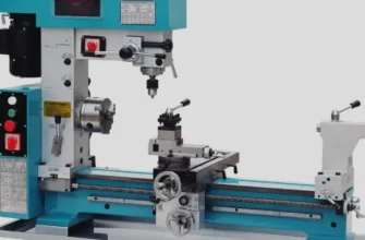
Understanding the Lathe Machine Structure
A lathe machine might seem complex, but its structure is quite logical. It’s built on a sturdy foundation called the bed of the lathe, which ensures stability and alignment for all other components. The main working parts of a lathe machine are mounted on this bed.
These key parts include the headstock, which holds and rotates the workpiece via the main spindle; the tailstock, which supports the other end; and the carriage, which moves the cutting tool. Each component works together, making the lathe a powerful and precise machine tool. Let’s explore how these parts function.
Overview of Lathe Design and Function
The basic principle behind a lathe machine is simple yet effective. It works by rotating a workpiece on its axis while a cutting tool is fed into it to remove material. This creates a symmetrical, cylindrical shape. The specific lathe design allows for incredible precision and a variety of operations.
At its core, the workpiece spins, but the magic happens with the controlled movement of the tool. This movement can be parallel to the axis of the lathe to reduce the diameter, or perpendicular to it to create a flat face. You can also create tapers and threads by adjusting the tool’s path.
This fundamental interaction between the rotating workpiece and the guided cutting tool is what allows a lathe to perform so many different tasks. From simple turning to complex shaping, the design ensures you have control over every cut.
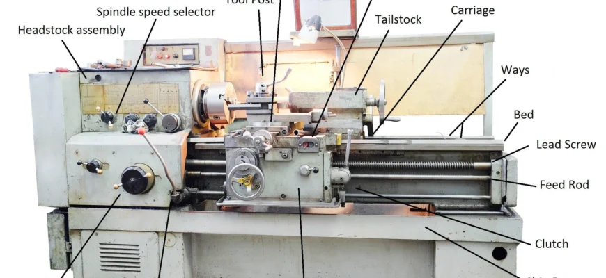
Labeled Lathe Diagram: Identifying Key Components
If you were to look at a labeled lathe diagram, you would see how all the components fit together. The lathe machine is primarily organized along a horizontal bed. On the left end of the lathe, you’ll find the headstock, which houses the motor and spindle. On the opposite end is the tailstock, which can be moved to support longer workpieces.
Between these two points is the carriage, which moves along the bed and carries the cutting tool. The carriage itself is an assembly of smaller parts that give you fine control over the tool’s position. Understanding where each of these parts of lathe machine is located is key to operating it safely and effectively.
Here is a simple breakdown of the main components and their locations:
| Component | Location on the Lathe |
|---|---|
| Headstock | Fixed on the left side of the bed |
| Tailstock | Movable on the right side of the bed, opposite the headstock |
| Bed | The base or foundation of the entire machine |
| Carriage | Sits on and moves along the bed, between the headstock and tailstock |
| Chuck | Attached to the spindle on the headstock |
| Lead Screw | Runs along the front of the bed |
The Bed – Foundation of Stability
The lathe bed is the backbone of the entire machine tool. Typically made from heavy-duty cast iron, it provides the rigidity and stability needed for precise machining. Its primary job is to support and align all the other major components, from one end of the lathe bed to the other.
A strong, flat bed is critical for achieving a good surface finish on your workpiece, as it prevents vibrations that could spoil the cut. Different types of lathes may have beds of varying lengths and designs, but their foundational role remains the same. Let’s look closer at its features.
Features and Role of the Lathe Bed
The lathe bed serves as the primary structural component of the machine. Made from cast iron due to its excellent vibration-damping properties and durability, the bed ensures that all other parts remain in perfect alignment. It’s the base upon which the headstock, tailstock, and carriage are mounted.
This essential part of the lathe features precisely machined guideways. These are tracks that the carriage and tailstock slide along. The accuracy of these guideways directly impacts the accuracy of the entire lathe. They must be perfectly straight and parallel to the axis of the main spindle.
Key roles of the lathe bed include:
- Providing a solid, stable foundation for the entire machine.
- Ensuring accurate alignment between the headstock and tailstock.
- Guiding the movement of the carriage for smooth and precise cuts.
- Absorbing vibrations generated during the machining process.
Guideways and Support Systems
The guideways are the precision-machined tracks on the top of the lathe bed. Their main purpose is to guide the carriage and tailstock, ensuring their smooth movement along the length of the lathe. Think of them as rails that keep everything perfectly aligned with the workpiece.
This support system is critical for accuracy. Any imperfections in the guideways will be transferred to your workpiece, resulting in errors. The guideways allow the carriage, which holds the tool post and cutting tool, to travel parallel to the workpiece’s axis for turning operations.
Proper maintenance of the guideways is essential. They must be kept clean and lubricated to prevent wear and tear. Worn or damaged guideways can cause the carriage to move unevenly, affecting the quality of your cuts and the overall precision of the machine.
Headstock Assembly Explained
The headstock is one of the most important components of a lathe machine, located on the left side of the bed. It acts as the control center for power transmission. Inside the headstock, you’ll find the main spindle, a gear train, and mechanisms to control the spindle speed.
This assembly takes power from the motor and delivers it to the workpiece. The gears allow you to select different speeds, which is crucial for working with various materials and diameters. From the main spindle at the end of the headstock to the internal gears, this assembly is the heart of the lathe.
Main Spindle Mechanism
The main spindle is the rotating shaft of the headstock. It’s a hollow but very strong component designed to hold and rotate the workpiece accurately. The quality of the spindle and its bearings directly influences the precision of the machine.
At the front of the lathe spindle, you’ll find a mounting point for chucks or faceplates. This is where the workpiece is secured. The entire spindle rotates along the central axis of the lathe, providing the motion needed to cut the material.
Controlling the spindle speed is vital for different operations. For example, larger diameter workpieces require slower speeds, while smaller ones can be turned much faster. The spindle’s ability to maintain a consistent speed under load is a mark of a good quality lathe.
Gearbox and Drive System
The drive system of a lathe is responsible for power transmission from the electric motor to the spindle. This system almost always includes a gearbox, which is a critical component for controlling the rotational speed of the workpiece.
The gearbox contains a set of gears that can be engaged in various combinations. By shifting levers on the headstock, an operator can select from a range of different speeds. This versatility allows you to optimize the cutting conditions for different materials, tool types, and operation requirements.
Without a functional gearbox, you would be stuck with a single speed, severely limiting the lathe’s usefulness. Modern lathes have sophisticated gearboxes that offer a wide spectrum of speeds, enabling both high-speed finishing cuts and low-speed, high-torque cuts for heavy material removal.
Bearings and Speed Control
For the spindle to rotate smoothly and accurately, it relies on high-quality bearings. These components reduce friction and support the spindle, ensuring it can handle the forces generated during machining without wobbling. Many lathes use precision ball bearings or roller bearings for this purpose.
The bearings are crucial for maintaining accuracy at both high and low speeds. Good bearings ensure that the speed of the spindle remains constant and that there is no “play” or movement that could affect the final dimensions of the workpiece.
Effective speed control is managed through the gearbox and drive system, but the bearings are what make that control meaningful. They allow the spindle to perform reliably across its entire speed range, from roughing cuts that require high torque to finishing passes that demand high rotational speed.
Tailstock Function and Uses
The tailstock sits on the opposite end of the lathe from the headstock and plays a vital supporting role. Its primary function is to support the free end of the workpiece, especially when machining long or slender parts. This support prevents the piece from bending or vibrating under the pressure of the cut.
You can mount different accessories in the tailstock, such as a live center for support or a drill chuck for drilling holes into the center of the workpiece. It is also essential for operations like taper turning by offsetting it from the centerline.
Construction and Adjustment Methods
The construction of the tailstock is robust, designed to withstand significant pressure. It consists of a body that sits on the lathe bed’s guideways and a spindle or quill that can be moved in and out with a handwheel. This allows for fine adjustment when setting up a workpiece.
The entire tailstock assembly can be unlocked and slid along the bed to accommodate workpieces of different lengths. Once positioned, it’s clamped firmly in place. A key feature is its ability to be set at the exact same centre height as the headstock spindle, ensuring perfect alignment.
For some operations, like taper turning, the tailstock can be intentionally offset. This slight misalignment causes the cutting tool to cut a cone shape instead of a straight cylinder. The ability to adjust the tailstock both along and across the bed makes it a very versatile part of the lathe.
Applications in Drilling and Support
One of the most common applications for the tailstock is providing support for long workpieces. To do this, you typically use a live center—a hardened point with bearings that can rotate with the workpiece. This prevents friction and heat buildup at the contact point.
This support is crucial for maintaining accuracy, as it stops the end of the workpiece from deflecting away from the cutting tool. Without it, turning a long, thin shaft would be nearly impossible.
Besides support, the tailstock is essential for drilling operations.
- Holding Drill Chucks: A drill chuck can be fitted into the tailstock’s quill to hold drill bits.
- Centering and Drilling: By advancing the tailstock quill with the handwheel, you can drill precise holes into the center of the rotating workpiece.
- Reaming and Tapping: The tailstock can also be used to hold reamers and taps for finishing holes accurately.
Carriage — Movement and Control
The carriage is the workhorse of the lathe, as it’s responsible for holding and moving the cutting tool. It sits on the lathe bed and can travel along its length, controlling the movement of the carriage either manually or with a power feed.
This assembly is made up of several key parts, including the saddle, cross slide, compound rest, and tool post. Attached to the front of the carriage is the apron, which houses the controls for its movement. Understanding the carriage is key to controlling your cuts. Let’s look at its components in more detail.
Saddle, Cross-slide, and Compound Rest
The saddle is the H-shaped casting that sits on top of and slides along the lathe bed’s guideways. It forms the base for the rest of the carriage assembly.
Mounted on top of the saddle is the cross slide. This component allows for tool movement perpendicular to the axis of the lathe. You use the cross slide to set the depth of your cut and to perform facing operations, which create a flat surface on the end of the workpiece. Precise control of the cross slide is essential for achieving an excellent surface finish.
The compound rest sits on top of the cross slide and can be swiveled to any angle. It provides a third, smaller axis of tool movement. This feature is particularly useful for cutting short tapers or angles, giving you fine control over the tool’s path.
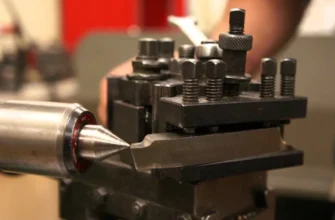
Tool Post and Cutter Mounting
The tool post is mounted on the compound rest and is the component that directly holds the cutting tool. Its job is to clamp the tool securely, preventing it from moving or vibrating during a cut. There are several styles of tool posts available.
Many lathes use a simple, single-tool post, while others feature a four-way or turret-style post that can hold multiple tools at once. This allows for quick tool changes between different operations. More advanced lathes may use quick-change tool holders, which allow for fast and precise mounting of various tools.
The rigidity of the tool post is critical. Any flex or movement here will compromise the accuracy and quality of your cuts. A solid tool post ensures that the tool movement is solely controlled by the carriage, cross slide, and compound rest, just as you intend.
Apron, Power Feed, and Controls
The apron is the part of the carriage that hangs down in front. It’s essentially a gearbox that contains the controls for both manual operation and the power feed mechanism. All the levers and handwheels you need to move the carriage are located here.
When you turn the large handwheel on the apron, you move the entire carriage assembly along the bed manually. For longer, more consistent cuts, you can engage the power feed. This feature uses a clutch system inside the apron to connect the carriage to the rotating feed rod or lead screw.
The power feed provides a smooth, automated movement for turning and facing operations, resulting in a much better surface finish than you could achieve by hand. The apron contains the selectors and levers to engage or disengage this feed and control its direction, giving you complete command over the carriage.
Chuck System and Workpiece Handling
The chuck is the primary device used for workpiece handling on a lathe. Its purpose is to securely grip the workpiece while it is being rotated by the spindle. A proper chuck system is essential for both safety and precision, as it ensures the material doesn’t slip or fly out during machining.
The headstock spindle is responsible for rotating the workpiece, but it’s the chuck that actually holds it. Besides chucks, other devices like faceplates and mandrels can also be used, depending on the shape and size of the part. Let’s examine how these systems work.
Purpose and Operation of the Lathe Chuck
The main purpose of a lathe chuck is to secure a workpiece to the rotating shaft of the headstock spindle. The chuck’s jaws clamp down on the material, holding it firmly in place so that it rotates true with the center axis of the lathe.
Operation is straightforward. You use a special key, called a chuck key, to tighten or loosen the jaws. As you turn the key, internal gearing moves the jaws in or out simultaneously (on a three-jaw chuck) or independently (on a four-jaw chuck). This allows you to clamp onto various sizes of round or square stock.
The effectiveness of a chuck depends on its type and the job at hand. Key functions include:
- Securely gripping the workpiece to prevent slipping during cuts.
- Centering the workpiece accurately on the lathe’s axis of rotation.
- Adapting to different shapes and sizes of material, depending on the type of lathe and chuck.
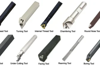
Types of Chucks (Three-jaw, Four-jaw, Collet)
Not all chucks are the same; there are various types designed for different tasks. Understanding them is important when selecting the right lathe parts for your project. The most common types are the three-jaw, four-jaw, and collet chuck.
A three-jaw chuck is self-centering, meaning all three jaws move together. It’s great for quickly clamping round or hexagonal stock. A four-jaw chuck has jaws that move independently, allowing you to clamp irregular shapes or to center a workpiece with extreme precision. The collet chuck uses a collet—a type of sleeve—to grip the workpiece with very high accuracy and is ideal for small-diameter parts.
Here’s a quick comparison:
- Three-jaw chuck: Fast and convenient for round stock.
- Four-jaw chuck: Highly versatile for irregular shapes and precision centering.
- Collet chuck: Best for high-precision work on small, finished parts.
- Each type offers a unique advantage for specific machining needs.
Faceplate and Mandrel Accessories
Sometimes, a workpiece is too large or irregularly shaped to be held in a chuck. This is where accessories like a faceplate come in handy. A faceplate is a flat, circular plate that bolts to the end of the spindle. It has slots and holes that allow you to clamp the workpiece directly to its surface.
Faceplates are ideal for parts with large diameters or odd shapes that a chuck can’t grip. You use clamps, bolts, and angle plates to secure the workpiece firmly before machining.
Another useful accessory is a mandrel. A mandrel is a tapered or expanding shaft that is used to hold a workpiece that has already been bored or drilled. The workpiece fits over the mandrel, which is then mounted between the headstock and tailstock. This allows you to machine the outside diameter perfectly concentric to the inside hole.
The Feed Mechanism
The feed mechanism is what gives a lathe its ability to make automated, precise cuts. This system consists of a lead screw and a feed rod, which are driven by a gear train connected to the headstock. This mechanism controls the movement of the carriage along the bed.
Different lathe models often have variations in their feed systems. For instance, some smaller lathes might only have a lead screw, while larger industrial machines have both a feed rod for general turning and a separate lead screw for thread cutting. The engagement of these rods is controlled by the half nut and other levers on the apron.
Lead Screw and Thread Cutting
The lead screw is a long, threaded rod that runs from the headstock to the other end of the lathe. Its primary purpose is for thread cutting. It is a very precise component, as its accuracy directly determines the accuracy of the threads you cut.
To cut threads, you engage a mechanism called the half nut on the carriage apron. The half nut closes around the lead screw, causing the carriage to move a precise distance for each rotation of the spindle. The relationship between the spindle speed and the lead screw’s rotation is set by changing gears in the headstock.
This synchronized movement is the key to the thread machining process. By selecting the correct gear combination, you can cut a wide variety of thread pitches, both metric and imperial. The lead screw is typically used only for threading to preserve its accuracy.
Feed Rod and Power Transmission
For all other turning and facing operations, you use the feed rod. This is a long, key-slotted shaft that also runs along the front of the lathe. Its job is to handle the power transmission for the carriage’s automated movement during non-threading cuts.
The feed rod is connected to the apron’s internal gearing through a clutch system. When you engage the power feed lever, the clutch connects the apron to the rotating feed rod, causing the movement of the carriage. This allows for a smooth, consistent feed rate, which is essential for achieving a good surface finish.
Using the feed rod for general turning helps preserve the accuracy of the lead screw for its intended purpose of thread cutting. On some machines, like a turret lathe, the feed mechanism can be more complex to allow for automated multi-step operations.
Half Nut and Feed Selector
The half nut is a crucial component located within the apron. It is a split nut that can be opened and closed around the lead screw using a lever. Its sole purpose is to engage the carriage with the lead screw for thread cutting. It’s called a half nut because it’s made of two halves that clamp together.
The feed selector is another control on the apron that allows you to choose how the carriage is powered. You can use it to switch between longitudinal feed (moving along the bed) and cross feed (moving across the bed). This control determines which set of gears inside the apron is engaged with the feed rod.
Together, these lathe machine parts give you precise control over the carriage’s automated movement for various operations. You use the half nut for threading and the feed selector for all other power-fed movements.
Specialized Components and Attachments
Beyond the basic components, many specialized attachments can enhance a lathe’s capabilities, particularly in manufacturing industries. A steady rest and a follower rest, for example, provide extra support for long or thin workpieces. A catch plate is used in certain setups to drive the workpiece.
Other important components include the coolant system and the chip pan, which help manage heat and waste. Parts that see a lot of wear, like cutting tools, bearings, and belts, are the most frequently maintained or replaced items. Let’s look at some of these specialized parts.
Steady Rest and Follower Rest
A steady rest is a device that provides support to a long workpiece at a fixed point along the lathe bed. It clamps directly to the bed and has three adjustable jaws that are brought in to gently touch and support the workpiece. This prevents the part from whipping or vibrating during machining.
The steady rest is particularly useful when you need to machine the end of a long shaft or when working with parts of large diameters that extend far from the chuck. It acts like a temporary tailstock, providing rigidity in the middle of a part.
A follower rest serves a similar purpose but is different in design and application. It bolts to the carriage and moves along with the cutting tool. It typically has two jaws that “follow” the tool, providing immediate support right behind the point of the cut. This is ideal for turning long, slender shafts to prevent them from bending under the tool pressure.
Catch Plate and Backplate
A catch plate, also known as a drive plate, is used as part of the drive system when turning a workpiece between centers. It bolts to the spindle nose and has a slot or pin that engages with a “dog,” which is clamped to the workpiece. This setup ensures positive power transmission without relying on a chuck.
This method is often used for high-precision turning because it eliminates any inaccuracies that might be present in a chuck. The catch plate provides a direct, robust connection between the spindle and the workpiece.
A backplate is an adapter used to mount a chuck onto a spindle nose that doesn’t have a direct-mount system. The backplate is machined to fit the spindle perfectly, and then the chuck is bolted to the backplate. This ensures the chuck runs true and is securely fastened to the spindle.
Coolant, Lubrication, and Chip Pan
A coolant system is a vital accessory for most metal-cutting operations on a lathe. It pumps a stream of fluid directly onto the cutting tool and workpiece. This has two main benefits: it cools the tool to extend its life and flushes away chips from the cutting zone. The use of coolant often results in a better surface finish.
Proper lubrication is also essential for the health of the machine tool itself. The guideways, gears, and bearings all require regular oiling to reduce friction and prevent wear. Many lathes have built-in lubrication systems to make this easier.
Finally, the chip pan is a simple but important feature. It is a large tray located at the bottom of the lathe designed to catch the metal chips and excess coolant produced during machining. This keeps the workshop floor clean and safe and makes cleanup much easier.
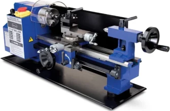
Comparing Manual and CNC Lathe Parts
The biggest difference between a manual lathe and a CNC lathe machine is automation. While a manual lathe relies on an operator’s skill for every manual operation, CNC lathes are controlled by a computer using numerical control. This allows for incredible precision and repeatability.
Many of the basic parts are similar, but modern lathes with CNC technology have additional components like servo motors, ball screws, and sophisticated control panels instead of handwheels and levers. Let’s compare the control systems and other specific mechanisms.
Distinctions in Control Systems
The primary distinction between manual lathes and CNC machines lies in the control system. A manual lathe uses handwheels and levers for every movement. The operator is in direct control, making it a hands-on, skill-based manual operation.
In contrast, a CNC lathe is governed by a pre-written computer program. This program dictates every movement of the tool, spindle speed, and coolant flow. This automation removes the potential for human error and allows for the creation of highly complex shapes with perfect consistency.
This table highlights the core differences between the various types of control systems:
| Feature | Manual Lathe | CNC Lathe |
|---|---|---|
| Control Input | Handwheels, levers, and operator skill | G-code program fed into a computer controller |
| Movement | Operator manually moves the carriage and cross slide | Servo motors drive ball screws for precise, automated movement |
| Repeatability | Depends on operator consistency | Extremely high and consistent for every part |
| Complexity | Limited to what an operator can produce manually | Can produce very complex geometries with ease |
CNC-Specific Mechanisms and Tool Holders
CNC lathes feature several mechanisms not found on manual machines, all designed for automation and efficiency. Instead of a simple tool post, CNC machines typically use an automatic tool turret. This turret can hold many different tool holders and can rotate to change tools in seconds, as instructed by the program.
These machines also use high-precision ball screws instead of traditional lead screws. Ball screws have very little backlash, allowing for extremely precise and repeatable movements controlled by servo motors. This is essential for the accuracy required in mass production.
Other CNC-specific features often include:
- Hydraulic Chucks: These provide automated and consistent clamping pressure on the workpiece.
- Chip Conveyors: An automated system that removes chips from the machine to keep it running continuously.
- Automatic Bar Feeders: A mechanism that feeds new raw material into the lathe for uninterrupted production.
Conclusion
In summary, understanding the main components of a lathe is crucial for anyone interested in machining. Each part, from the bed that provides stability to the headstock that drives the main spindle, plays a significant role in the overall functionality of the machine. By familiarizing yourself with these elements, you can enhance your skills and ensure proper maintenance, ultimately leading to better performance and results in your projects. Whether you’re working with manual or CNC lathes, this knowledge empowers you to make informed decisions about your tools and techniques. If you’re ready to dive deeper into the world of machining, consider exploring our resources or reaching out for a consultation to elevate your skills further.
Frequently Asked Questions
What are the most important components to maintain on a lathe?
Regular maintenance of your lathe machine should focus on the parts that see the most wear. This includes lubricating the guideways, checking the spindle bearings for play, and keeping the lead screw clean and oiled. Also, ensure the coolant system is functioning properly to protect your tools.
How does the carriage operate and what does it do?
The carriage holds the cutting tool and controls its movement. It can be moved along the lathe bed through manual operation of a handwheel on the apron or automatically via power feed. The cross slide provides perpendicular tool movement, allowing you to control the depth of cut and perform facing operations.
Which parts are responsible for holding and rotating the workpiece?
The headstock spindle is the rotating component, but the lathe chuck, mounted on the end of the headstock‘s main spindle, is what actually holds the workpiece. The chuck’s jaws grip the material tightly, ensuring it spins securely and accurately with the spindle during machining.