Ward capstan and turret lathes represent a cornerstone of British manufacturing heritage, embodying decades of precision engineering and innovative design. These semi-automatic machines revolutionized production metalworking by enabling operators to perform complex machining sequences with minimal setup time, making them indispensable to industries ranging from automotive manufacturing to precision component production. The Ward capstan and turret lathe stands as a testament to engineering excellence during the mid-20th century, when British machine tool makers dominated global markets.
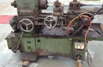
For restorers, collectors, and workshop enthusiasts, Ward lathes hold particular appeal. Their robust construction, mechanical elegance, and proven reliability mean that examples from the 1940s through 1970s remain fully operational today. Unlike many vintage machines that become ornamental, a restored Ward lathe can handle serious production work, perform precision cutting operations, and serve as an educational tool for understanding the principles of metal-cutting automation.
This comprehensive guide covers everything from the historical context of H.W. Ward & Co’s innovative engineering to detailed restoration procedures, technical specifications, and practical operating guidance. Whether you’re evaluating a used machine, planning a restoration project, or simply curious about these remarkable machines, this guide provides the authoritative information you need.
Who Was H.W. Ward & Co.? – The Innovators Behind the Brand
The Birth of a Machine Tool Manufacturer
H.W. Ward & Co stands as one of Britain’s most significant yet historically underappreciated machine tool manufacturers. Founded in 1889, the company began operations at premises in Ladywood Road, Edgbaston, Birmingham, during a period of remarkable industrial expansion across the English Midlands. The company’s early years reflected the ambitions of industrial Britain: engineers and entrepreneurs recognized that the future of manufacturing lay not in traditional, general-purpose machines, but in specialized equipment designed for specific production challenges.
During its initial decades, H.W. Ward & Co manufactured a diverse range of machine tools – drilling machines, grinding equipment, and various lathe types. However, this broad product strategy proved limiting. By 1895, the company relocated to larger premises on Lionel Street in the heart of Birmingham’s industrial district. The establishment of H.W. Ward & Co as a Limited Company in 1908 marked a turning point, enabling capital investment and expansion.
The Specialization Decision of 1912
In 1912, company leadership made a pivotal strategic decision that would define the organization’s identity for the next seven decades: concentrate exclusively on capstan and turret lathe design and manufacture. This was no arbitrary choice. Market analysis revealed that capstan and turret lathes represented the future of volume production. The decision required new facilities, and in 1912, Ward acquired purpose-built works at Selly Oak in Sellie Park, Birmingham – an expansion of a facility already serving the growing demand for semi-automatic production machinery.
This specialization proved remarkably prescient. By 1900, Ward had already exhibited a “combination” turret lathe at the Paris Exhibition, showcasing their understanding of sophisticated lathe design. A combination machine allowed operators to perform both long and short work by incorporating both a short turret slide and a full lathe saddle – an innovation that increased versatility dramatically. The 1912 decision to focus exclusively on this category transformed Ward into a specialist maker, elevating them to the highest tier of British machine tool engineering.
Association with British Industry & Aircraft Production
H.W. Ward & Co did not operate in isolation. In 1917, the company joined the Associated British Machine Tool Makers (ABMTM), a trade association comprising Britain’s finest precision machine builders: Butler, Churchill, Kendall & Gent, Lang, Parkinson, and others. Working through this association, Ward machines reached markets from Australia to Canada. The collective selling agency established at 17 Grosvenor Gardens in London coordinated international distribution, helping British manufacturers compete globally.
During World War II, Ward facilities contributed to aircraft manufacturing initiatives, further cementing the company’s reputation for precision and reliability. Throughout the 1920s, 1930s, 1940s, and 1950s, Ward lathes earned recognition for their robust construction, sophisticated automatic features, and ability to maintain accuracy across extended production runs – precisely the qualities required for high-volume military and civilian manufacturing.
Post-War Production & Later History
After World War II, Ward continued manufacturing through the 1950s and 1960s, a period when British machine tools still dominated world markets. The company produced increasingly sophisticated models with improved speed ranges, better indexing mechanisms, and more flexible tooling systems. Production continued into the 1970s, when competition from German, Italian, and Japanese manufacturers gradually transformed the competitive landscape.
In 1984, F Bamford & Co acquired H.W. Ward & Co, establishing themselves as the primary spare parts supplier for Ward machines worldwide. This acquisition proved crucial for owners and restorers, as Bamford maintained original drawings and specifications, manufacturing replacement parts according to original specifications. The Wickman Group subsequently acquired Ward operations from F Bamford & Co, continuing the legacy of supporting these machines globally.
Today, original Ward spare parts remain available through specialist suppliers, and the robust construction of Ward machines ensures that examples from seven decades ago continue operating reliably in workshops, educational institutions, and private collections across the globe.
What Is a Capstan & Turret Lathe? – Definitions & Distinctions
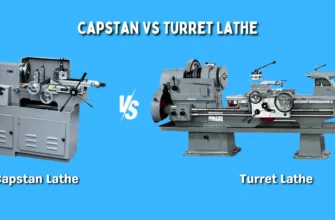
Understanding Capstan vs. Turret Lathe: Core Structural Differences
The terms capstan lathe and turret lathe are often used interchangeably, particularly in British and Commonwealth machine tool contexts. However, technical precision demands that we understand the subtle but important distinctions that define each category.
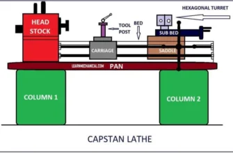
A turret lathe features a rotating, indexable toolholder (the turret) mounted on a relatively short slide attached to the saddle. The turret typically holds six tools arranged hexagonally, though earlier designs sometimes featured square configurations. When the turret rotates to index to the next tool, minimal material is removed in this transition – the machine is designed for efficient sequential operations on a single workpiece held in a chuck.
A capstan lathe represents a technical variant where the turret is mounted on a longer ram or slide, providing greater tool stroke and allowing for more substantial material removal and complex work sequences. The capstan turret’s extended travel enables simultaneous facing and turning operations that a standard turret lathe might require two separate setups to accomplish.
In Ward’s terminology and marketing literature, the distinction often blurred together. Many Ward machines are classified as “capstan” even when they feature characteristics that engineers might classify as “turret.” This reflects the practical reality that Ward designed sophisticated machines occupying a middle ground between pure capstan and pure turret configurations.
How the Turret Head Functions
The rotating turret head represents the engineering innovation that makes these machines possible. Unlike a traditional center lathe where the operator must manually change tools, stop the spindle, unclamp and replace the tool, and reset work holding for each operation, the turret lathe automates this process mechanically.
The turret carries multiple tools simultaneously. After each machining operation, the turret indexes (rotates) to present the next tool to the work. Modern turret heads use an automatic indexing mechanism – typically a ratchet-and-pawl arrangement or hydraulic indexing system – that locks the turret firmly in place after rotation. This positive indexing ensures that tool height and position remain consistent across production runs, directly contributing to part accuracy and repeatability.
Tooling arrangement on the turret follows precise geometric logic. Each of the six hex turret positions holds a specific tool. The operator arranges tools in sequential order corresponding to the required machining operations. Common arrangements include:
- Station 1: Facing tool (to establish part length reference)
- Station 2: Turning tool (primary diameter reduction)
- Station 3: Drilling tool (hole center preparation)
- Station 4: Boring bar (hole final diameter sizing)
- Station 5: Threading tool or grooving tool
- Station 6: Parting tool (separating finished part from raw material)
This systematic arrangement eliminates operator guesswork and ensures consistent, repeatable results across hundreds or thousands of identical parts.
Typical Industrial Use Cases
Ward turret and capstan lathes found applications across virtually every metal-manufacturing sector of the 20th century:
Automotive Manufacturing: Engine components, transmission parts, fasteners, and hydraulic valve bodies benefited from the high-speed, high-accuracy capabilities of turret lathes. A single machine could produce thousands of identical components daily.
Precision Engineering: Ball bearing races, pump shafts, spindle components, and similar precision parts required the repeatability and speed that turret lathes provided economically.
Firearms & Ordnance: Ammunition components, firing mechanisms, and breech assemblies depended on turret lathe efficiency and accuracy.
Electrical Components: Motor shafts, switch housings, and other electrical equipment components represented high-volume applications where turret lathe economics made manufacturing viable.
Plumbing & Building Products: Brass fittings, valve bodies, and pipe components produced by the millions used turret lathe production.
General Component Manufacturing: Countless small metal parts – from eyebolts to clevis pins to standard bolts and screws – emerged from turret lathe production.
Ward machines typically handled components ranging from 1⁄4-inch to 5-inch diameter bar stock, with tool travel ranging from 3 to 12 inches, covering the sweet spot for high-volume production where investment in dedicated single-purpose machines wasn’t economically justified.
Which Machines Ward Specialized In
Ward’s product line emphasized mid-range “combination” turret lathes – machines large enough for serious production work but small enough to fit workshop floor spaces efficiently. Models like the 2A, 2B, 3A, and 3B represented the company’s bread-and-butter offerings, used by manufacturers globally. Larger models such as the 5C and 7C series addressed manufacturers requiring extended tool travel and heavier cutting capabilities.
Ward did not compete in the ultra-small hobby-machine market nor in massive heavy-duty production turret lathe territory. Instead, the company positioned itself as the premium manufacturer for workshop-scale, high-speed capstan machines that delivered precision, reliability, and operator efficiency.
Alternate Names & Industry Terminology
The terminology surrounding these machines reflects international variations and historical evolution:
- Capstan lathe: The predominant British and Commonwealth term
- Turret lathe: The American terminology, now increasingly universal
- Combination lathe: Specifically describes machines with both turret and saddle
- Semi-automatic lathe: Emphasizes the partial automation (automatic turret indexing and feed) alongside manual operations (part clamping, coolant control)
- Chucking lathe: Descriptive term emphasizing that parts are typically chucked rather than center-mounted
- Production lathe: Generic industrial description
Typical Lifespan & Longevity Factors
Understanding how long a Ward lathe remains productive is essential for restoration decisions.
Build Quality Foundation: Ward built these machines to industrial standards that mandated reliability through thousands of operating hours. Cast iron beds, precisely scraped slideways, and hardened steel components meant that the fundamental machine structure resisted wear far longer than modern, lighter-duty equipment.
Expected Service Life: With proper maintenance and reasonable usage, a Ward lathe from the 1940s-1960s can expect 20,000–50,000 productive operating hours before major components require refurbishment. Some machines have logged 100,000+ hours and remain serviceable.
Primary Wear Points:
- Turret Indexing Plate: The mechanism that rotates and locks the turret experiences wear as millions of index cycles accumulate. Backlash develops gradually – initially imperceptible, eventually affecting tool positioning accuracy.
- Spindle Bearings: Continuous rotation under load creates gradual bearing wear. Modern lubrication prevents catastrophic failure but doesn’t prevent gradual clearance increases.
- Slideways & Gibs: The precision-scraped surfaces that guide the cross-slide and turret saddle accumulate wear patterns. Metal-to-metal sliding under coolant creates micro-abrasion.
- Bar Feed Mechanisms: Components that automatically advance bar stock (on machines equipped with bar feeders) experience fatigue and wear after thousands of cycle operations.
- Collet Chuck: Repeated clamping and unclamping gradually damages the collet’s gripping surfaces.
Longevity-Determining Factors:
- Maintenance consistency: Machines receiving regular oil changes, coolant management, and adjustments last proportionally longer
- Operating temperature control: Machines in temperature-stable environments suffer less thermal expansion/contraction damage
- Coolant quality: Clean, properly formulated coolant dramatically extends slideaway life
- Load discipline: Machines used within design parameters outlast those pushed to maximum capacity continuously
- Spindle speed: Lower average spindle speeds reduce bearing wear rates
- Environment: Dry, dust-controlled environments slow corrosion and wear
A properly maintained Ward lathe represents a multi-generational investment – machines can easily remain productive for 40–60 years and beyond with appropriate restoration and maintenance.
Ward Capstan & Turret Lathe Model Overview – All Major Types
Ward 2A / 2B Series
The Ward 2A represents the company’s classic entry into the combination turret lathe market and became one of their longest-running successful designs. The “2A” designation traditionally indicated a machine with approximately 2-inch (center height), though actual swing capacity typically reached 3–4 inches.
Technical Characteristics:
- Center height: approximately 165–170mm (6.5 inches)
- Spindle bore: 41mm (standard Ward sizing)
- Spindle speeds: 60–2,520 rpm (12–14 speeds available through belt and gearing)
- Turret capacity: 6 tools in automatic hexagonal turret
- Collet capacity: Ward 403 collets (1⁄4-inch to 1-inch bar stock typical)
- Motor power: 3–5 hp depending on variant
The 2B variant represented a later development, incorporating refinements to the indexing mechanism and slightly improved spindle bearing design. Both models proved phenomenally popular – thousands were manufactured across the 1940s–1960s.
Ward 3A / 3B Series
Slightly larger than the 2 series, Ward 3A and 3B machines addressed manufacturers requiring increased swing capacity and longer tool travel. These models featured:
- Center height: 175–180mm approximately
- Extended turret slide travel
- Increased spindle power
- Support for larger collet sizes (up to 1-1⁄4 inches typical)
- Similar automatic indexing and feed systems
The 3 series appeared frequently in mid-volume production environments where the 2 series capacity proved marginal but full-size machines remained economically unjustifiable.
Ward 5C / 7C / 7B Series
The larger capacity models – particularly the 5C and 7C – represented Ward’s answer to manufacturers requiring extended spindle capacity and heavy-duty cutting capability. These machines featured:
- Center heights ranging from 200–250mm
- Extended bar capacity (1-1⁄2 to 2-1⁄2 inches typical)
- Longer turret travel (6–10 inches common)
- Heavy-duty spindle bearings for increased cutting forces
- More powerful motors (10–15 hp typical)
The 7B variant appeared in Ward’s late production runs and represented refinement of earlier 7C designs, incorporating updated control systems and improved coolant delivery.
Ward 50s Series (1940s–1950s Production)
The Ward 50s series designation appears in company literature and refers to machines manufactured during the 1940–1950 period. These machines represented the transitional design phase where Ward was refining indexing mechanisms, improving spindle bearing systems, and increasing speed ranges to compete with emerging international designs.
Models from this era typically featured:
- Single-pulley or multi-step pulley headstock configurations
- Manual or semi-automatic indexing (transitioning to fully automatic)
- 2A, 2B, 2DS, 3A, 3B, and 3DS variants
- AC or DC motor compatibility
- Collet chuck or chuck options
Size Classification & Applications:
| Model Series | Center Height | Bar Capacity | Primary Applications |
|---|---|---|---|
| 2A/2B | 165mm | 1/4″–1″ | Small components, mass production |
| 3A/3B | 175mm | 1/2″–1.25″ | Medium components, precision work |
| 5C/7C | 200–250mm | 1″–2.5″ | Larger parts, heavy-duty production |
| 50s Series | 165–200mm | Varies | Transitional models, diverse applications |
Typical Tooling Supplied:
Ward machines typically shipped with factory tooling packages including:
- Hexagonal automatic-indexing turret
- 6 turret tool stations with adjustable tool holders
- Automatic feed stops for controlled tool travel
- Cutting fluid/coolant system with distribution lines
- Collet chucks in standard sizes (typically 403 or equivalent)
- Initial set of collets (6–12 pieces standard)
- Manual or automatic bar feeder (optional)
- Original instruction manual and maintenance charts
Key Specifications of Ward Lathes – Comprehensive Reference
Dimensions & Working Capacity
The working capacity of any Ward machine represents the fundamental constraint defining suitable applications. Unlike modern CNC machines with straightforward diameter specifications, Ward machines featured variable capacity depending on which fixture was installed.
Center Height: This fundamental specification defined the maximum workpiece diameter that could be mounted in the chuck without the cutting tool fouling the bed. A 165mm center height allowed approximately 330mm swing (13 inches over bed), though actual usable diameter over the cross-slide (where most cutting occurred) was typically 200–220mm, considerably less.
Spindle Speeds: Ward machines provided multiple spindle speeds through belt-and-pulley combinations and internal gearing. A typical 2A machine offered 12–14 spindle speeds ranging from 60 rpm (for heavy cutting or large-diameter work) to 2,520 rpm (for finishing small components or threading). This speed range accommodated materials from soft aluminum to hard steel and tool materials from conventional high-speed steel (HSS) to early carbide inserts.
Turret Slide Travel: The longitudinal travel of the turret (along the length of the workpiece) ranged from 3–6 inches on smaller models to 8–12 inches on larger machines. This travel distance determined how long a part could be, which – combined with the collet capacity – defined the workpiece envelope.
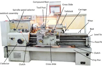
Turret Head & Carriage Specifications
Turret Configuration: Ward machines predominantly featured hexagonal turrets with 6 tool stations. Each station included threaded holes (typically 7⁄16″-20 or 1⁄2″-20) for mounting various tool holders. Some earlier Ward models featured square turrets with 4 positions, but hexagonal designs became standard during the company’s peak production years.
Indexing Mechanism: Automatic indexing mechanisms employed ratchet-and-pawl designs, where a spring-loaded pawl advanced through the turret’s indexing plate, rotating the turret one station per stroke. The positive locking mechanisms prevented turret rotation during cutting operations, critical for maintaining tool geometry and part accuracy.
Lever vs. Handwheel Operation: Earlier Ward models featured manual handwheel indexing, where the operator manually rotated the turret between operations. Mid-to-late production models incorporated automatic indexing actuated by cams on the ram mechanism – the turret automatically indexed when the ram returned from a cut. This automation dramatically reduced cycle time and operator fatigue.
Powertrain & Motor Systems
Motor Horsepower: Ward provided motors ranging from 3 hp on the smallest 2A models to 15 hp on the largest production machines. Motor sizing reflected the cutting forces anticipated during typical operations. Too small a motor limited depth-of-cut and feed rates; too large an motor consumed excessive power and generated heat.
Speed Ranges: The internal gearbox provided the multiple speed ranges necessary for optimal chip removal across different materials and operations. A typical gearbox provided the following speed selections via selector levers or belts:
- Low range: 60, 90, 120 rpm (heavy cutting, threading)
- Medium range: 250, 400, 600, 1000 rpm (general production)
- High range: 1500, 1800, 2520 rpm (finishing, small-diameter work)
Gearbox Configuration: Most Ward machines employed a sliding-gear or belt-drive configuration where the operator selected the desired range before the spindle engaged. Some later models incorporated infinitely variable speed drives using belt-pulley systems, anticipating CNC-era designs.
Weight, Footprint & Installation Requirements
Ward machines were substantially built cast-iron structures designed for floor mounting with concrete foundations in high-production environments.
Typical Machine Weights:
- Model 2A/2B: 3,500–4,000 lbs
- Model 3A/3B: 4,500–5,500 lbs
- Model 5C/7C: 7,000–9,000 lbs
Floor Space Requirements:
- Model 2A/2B: 8 feet long × 4 feet wide (approximate)
- Model 3A/3B: 9 feet long × 4.5 feet wide
- Model 5C/7C: 11 feet long × 5 feet wide
Installation Considerations: These machines required concrete foundations for vibration isolation, appropriate electrical service (typically 440V three-phase industrial power for larger models), coolant drain systems, and chips/swarf management infrastructure. Modern shops often require reinforced floors to accommodate these machines safely.
Comprehensive Specifications Table
| Specification | 2A/2B | 3A/3B | 5C/7C | Notes |
|---|---|---|---|---|
| Center Height | 165mm (6.5″) | 175mm (7″) | 200–250mm | Over bed swing = 2× center height |
| Max Swing | 330mm (13″) | 350mm (14″) | 400–500mm | Maximum workpiece diameter possible |
| Swing over Slide | 210–220mm (8–9″) | 230–240mm (9–10″) | 280–300mm (11–12″) | Practical cutting diameter |
| Spindle Bore | 41mm (1.625″) | 41mm | 50–60mm | Collet taper compatibility |
| Spindle Speeds | 60–2,520 rpm | 60–2,520 rpm | 40–1,500 rpm | 12–14 speed steps typical |
| Max Speeds | 2,520 rpm | 2,520 rpm | 1,500 rpm | Decreases with larger swing |
| Turret Positions | 6 (hex) | 6 (hex) | 6 (hex) | Automatic indexing |
| Turret Slide Travel | 150–200mm (6–8″) | 200–250mm (8–10″) | 250–300mm (10–12″) | Longitudinal tool movement |
| Collet Capacity | 1⁄4″–1″ | 1⁄2″–1.25″ | 1″–2.5″ | Ward 403 standard |
| Motor Power | 3–5 hp | 5–7.5 hp | 10–15 hp | Electrical service requirement |
| Machine Weight | 3,500 lbs | 4,500 lbs | 7,500 lbs | Floor loading consideration |
| Tooling Mounting | 7⁄16″–20 holes | 1⁄2″–20 holes | 1⁄2″–20 holes | Standard threading |
How a Ward Turret Lathe Works – Operation Explained
Turret Function & Station Indexing
Understanding how the turret functions mechanically reveals the elegant engineering that makes semi-automatic production possible. The turret’s automatic indexing system represents one of the most critical operational components.
Station-by-Station Indexing: The hexagonal turret holds six cutting tools arranged radially around a central rotating shaft. As the machine cycles, a mechanical linkage – typically an eccentric cam mechanism on the spindle’s main shaft or a separate motor drive – engages a pawl mechanism that advances through the turret’s indexing plate one tooth per complete cycle.
The indexing occurs at the end of the return stroke, when the turret ram retracts. As it retracts, a follower engages the indexing mechanism, causing the turret to rotate precisely 60 degrees (1⁄6 of a complete revolution), positioning the next tool directly in line with the spindle axis. A positive locking mechanism – typically a cone or detent arrangement – snaps the turret into the correct position and holds it rigidly throughout the cutting stroke.
This mechanical indexing eliminates operator error. The machine itself ensures that each tool stations automatically, without requiring the operator to manually position tools or verify alignment before each cut.
Tooling Arrangement for Multi-Stage Operations
The sequential arrangement of tools on the turret represents critical production planning. A typical arrangement for producing a precision fastener might flow like this:
Station 1 – Facing Tool: With the raw material (bar stock) clamped in the collet, the facing tool planes the end of the bar square, establishing a precise length reference. This first operation is crucial – all subsequent operations depend on accurate facing.
Station 2 – Roughing Turn: A high-speed turning tool reduces the bar diameter to a nominal size slightly oversize for finish requirements. Aggressive cutting removes maximum material efficiently.
Station 3 – Finish Turn: A precision turning tool produces the final diameter and surface finish. Lower speeds and lighter feeds than roughing ensure dimensional accuracy.
Station 4 – Drilling: A drill tool creates a center hole to a precise depth, preparing for secondary operations like threading or boring if required.
Station 5 – Threading: A threading die or tool cuts external or internal threads, producing precise helical surfaces.
Station 6 – Parting: A thin parting blade separates the finished component from the remaining bar stock, which is then fed into the next production cycle.
This logical progression – face, rough, finish, drill, thread, part – represents just one possible sequence. Complex components requiring boring, reaming, grooving, or other operations follow similar logical progressions tailored to specific part geometries and tolerances.
Capstan Slide Operation & Bar Work
The capstan slide represents the primary feed mechanism for longitudinal tool movement. Unlike a traditional lathe where the operator manually advances the cutting tool, the capstan slide provides automatic, controlled feed under power.
Automatic Traverse Mechanisms: The capstan slide connects to a feed mechanism that delivers consistent, operator-independent feed rates. Power-feed systems, either mechanical (through gears and shafts) or hydraulic (increasingly common in later designs), advance the turret at predetermined rates measured in inches per minute or millimeters per minute.
Bar Work Efficiency: With automatic feeding, the operator’s role transforms from tool manipulation to component loading/unloading and quality monitoring. A skilled operator can achieve cycle times of 30–60 seconds per component on smaller machines, or 2–5 minutes on larger, more complex setups. This dramatic improvement over manual lathe operation – which might require 5–15 minutes per component – explains the economic justification for turret lathe investment.
Repetitive Production Workflows: A production run on a Ward lathe typically follows this pattern:
- Setup phase (15–60 minutes): Install collets, load tooling into turret stations, adjust automatic stops, and verify tool heights and clearances through trial cuts
- Production phase: Load bar stock → machine cycles automatically → operator unloads finished parts and loads next stock
- Monitoring: Operator checks dimensions periodically (every 50–100 parts), adjusts tool offsets if dimensional drift occurs
- Tool changes: When cutting tools dull, rapid changeover (replacing a single turret station’s tool takes 2–5 minutes) resumes production
Typical Machining Cycle – Sequential Operations
A complete machining cycle on a Ward turret lathe unfolds in a precisely orchestrated sequence:
Facing Operation: The spindle rotates (typically 500–1000 rpm for steel), and the facing tool automatically traverses inward (feed rate typically 0.015–0.050 inches per revolution). The tool removes material from the end of the bar stock, creating a precise reference face. Cutting fluid flows to the tool, cooling it and carrying away chips. When the tool reaches the preset depth (controlled by a mechanical stop or operator-adjusted limit dog), the turret automatically retracts.
Turning Operation: As the turret retracts from the previous operation, the indexing mechanism engages, rotating the turret 60 degrees. The machine pauses briefly as the locking cone seats the turret in its new position. The spindle’s feed automatically engages again – the turning tool now in position advances radially inward as the spindle rotates, removing material in a helical path. Feed rates are carefully balanced: too aggressive and the tool or spindle stalls; too light and productivity suffers.
Drilling: The sequence continues with drilling, typically at lower spindle speeds (200–400 rpm) with less aggressive feed rates since drilling creates high cutting forces relative to turning. Drilling happens faster than one might expect – a 1⁄4-inch hole in steel, starting from solid material, might complete in 10–15 seconds.
Boring: Precision boring replaces drilling when hole diameter accuracy demands exceed what drilling alone provides. Boring bars offer adjustable tool position, allowing the operator to fine-tune hole diameter within 0.001 inches (25 microns).
Threading: External or internal threading proceeds at carefully reduced spindle speeds (typically 100–300 rpm), with the threading tool or die presenting precise helical paths. Threading forces are substantial, requiring robust machine rigidity.
Parting: The final operation employs a very thin blade that separates the finished component from the remaining bar stock. Parting forces are extreme relative to the blade thickness – the machine must be rigid, the blade sharp, and the part must be adequately supported to prevent deflection.
Throughout this cycle, cutting fluid flows continuously, cooling tools, carrying away chips, and lubricating workpiece-tool interfaces. A skilled setup ensures that each operation completes within its allocated time window without bottlenecks or collisions.
Cutting Fluids, Coolant Systems & Lubrication Points
Cutting fluid management is critical to Ward lathe operation and longevity.
Coolant Types: Ward machines typically operated with conventional soluble-oil cutting fluids – water-based formulations mixed to 5–10% concentration that provided cooling, lubrication, and chip flushing. Modern workshop practice increasingly substitutes synthetic fluids, semi-synthetic formulations, or even vegetable-based coolants that perform comparably while offering improved environmental profiles.
System Delivery: Most Ward machines featured pump-driven coolant delivery, circulating fluid from a reservoir through tool-mounted nozzles that directed coolant directly to the cutting action. More elaborate systems featured through-spindle coolant passages for drilling operations, delivering coolant directly through the drill flutes to the cutting edges.
Lubrication Points: Beyond cutting fluid, Ward machines required regular lubrication of slides, spindle bearings, and gearboxes. Typical maintenance schedules called for:
- Daily: Check oil levels in spindle bearing reservoirs and gearbox
- Weekly: Apply grease to turret indexing mechanism
- Monthly: Drain and refill apron sump (for crossslide lubrication)
- Quarterly: Drain spindle bearing oil and replace
- Semi-annually: Thoroughly flush all lubricant systems and replace with fresh oil
Original Ward maintenance manuals specified oil viscosities (typically ISO VG 32 for slideway lubrication, ISO VG 46 for gearbox, ISO VG 22 for spindle bearings), reflecting engineering analysis of bearing loads, slide wear patterns, and thermal characteristics.
Tooling & Attachments Used on Ward Lathes
Box Tools – The Foundation of Turret Tooling
Box tools represent the most fundamental turret lathe tooling, collectively comprising tools mounted in rigid steel holders that interface directly with the turret positioning mechanism. A box tool typically consisted of a steel body (the “box”) containing an indexable tool holder or ground high-speed steel tool.
The term “box” reflected the tool’s geometry – basically a metal box from which a precision tool protruded at the correct height and angle relative to the spindle axis. Box tools ranged from simple facing tools to complex arrangements with multiple cutting edges positioned to perform simultaneous operations.
Box tools offered several advantages:
- Rugged construction: Solid steel bodies resisted vibration
- Repeatability: Once installed, a box tool’s position remained constant across production runs
- Rigidity: Heavy steel mass dampened chatter common in lighter-duty turret systems
- Economic tooling: Mass-produced box tools were relatively inexpensive compared to custom configurations
Die Heads – Threading & Form Operations
Die heads represented more specialized tooling components that incorporated adjustable chasers (threading cutting tools) for producing threads. A typical die head mounted in a turret station and contained four or six chasers arranged radially, each presenting its edge to the rotating workpiece.
Die head design allowed for:
- Rapid threading: Threads completed in seconds rather than minutes
- Quality threads: Properly designed chasers produced smooth, accurate thread pitches
- Economic efficiency: A single die head replaced manually chased threading, cutting thread time dramatically
Ward machines often shipped with die head provisions in their turret stations, evidenced by special mounting holes and pressure-equalizing passages that allowed die chasers to open and close automatically as the ram traversed.
Reamers – Precision Hole Sizing
Reaming operations required specialized tools beyond simple drills. A reamer removes only 0.005–0.010 inches per side from a previously drilled hole, achieving diameter accuracy within 0.001–0.002 inches and superior surface finish (smooth bore walls).
Ward turret stations could accommodate:
- Hand reamers: Conventional cutting tools with straight or spiral flutes
- Boring bars with reaming inserts: Adjustable tool position allowed fine-tuning hole diameter
- Carbide reamers: Later production runs incorporated carbide tooling where harder-to-machine materials demanded superior edge retention
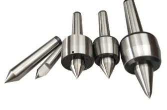
Collet Chucks – The Critical Workpiece Clamping Interface
The collet chuck represented perhaps the single most important accessory on any Ward turret lathe. This precision chuck holds and centers the bar stock with remarkable accuracy – concentricity (runout) typically within 0.001 inches on properly maintained equipment.
Collet Design: Ward standardized on Ward 403 collets, a tapered sleeve design where the collet slips over the bar stock and into a tapered bore in the chuck spindle. As a clamping lever is engaged, the collet is drawn further into the tapered bore, creating a symmetric clamping force that grips the bar without deflection.
Ward collets accommodated multiple bar diameters through interchangeable sleeves:
- Round collets: For standard circular bar stock (1⁄16 to 2+ inches in 1⁄64-inch increments)
- Square collets: For square bar stock (1⁄8 to 1.5-inch square typical)
- Hexagonal collets: For hex bar stock (3⁄32 to 1.5-inch A/F typical)
- Specialty collets: For rectangular, rectangular-with-corners, and specialized profiles
Collet sets typically included 12–24 sizes, allowing the operator to quickly switch between different bar materials and diameters without requiring lengthy setup procedures.
Automatic Stops – Controlling Tool Travel Distance
Automatic stops (sometimes called “limit dogs” or “stop pins”) represented elegantly simple devices that set the maximum tool traverse distance. These adjustable stops prevented tool overtravel, which could cause:
- Tool breakage
- Machine damage
- Out-of-specification parts
- Operator injury
Stops typically mounted on the turret ram or cross-slide and contacted fixed pins when the tool approached its limit, mechanically halting further advance. Spring-loaded mechanisms allowed smooth engagement without machine shock.
Bar Feeding Systems – The Optional Automation Layer
Bar feeders represented the ultimate automation refinement, allowing one operator to manage multiple machines simultaneously. A bar feeder mechanism:
- Held coiled or straightened bar stock in a magazine or hopper
- Advanced the bar one predetermined length (typically 0.5–3 inches) after each part was parted
- Positioned the fresh bar in the collet and initiated clamping automatically
Early bar feeders were pneumatically operated, using air-operated cylinders to feed stock. Later designs incorporated hydraulic or electric motors driving feed mechanisms. A well-tuned bar feeder reduced cycle time dramatically – operators no longer spent time manually loading each piece.
Turret Tool Holders – Standardized Mounting Interfaces
Ward turret stations featured standardized 7⁄16″-20 or 1⁄2″-20 threaded holes that accommodated various mounting systems:
- Solid tool posts: Rigid castings that clamped turning tools via set screws
- Quick-change tool posts: Allowed rapid tool substitution without full turret disassembly
- Boring bar holders: Specialized mounts for boring bars with fine-adjust mechanisms
- Drill chucks: For mounting drills without threading-tool mounts
- Die holder blocks: Positioned die heads at precise angles and heights
Rare & Collectible Ward Accessories
Certain Ward accessories have become highly sought by collectors and restoration enthusiasts:
Original Control Levers & Handwheels: Period-correct replacement levers, feed rate controls, and handwheels carry surprising scarcity value, particularly in original finish. Well-preserved examples with legible Ward & Co markings command premium pricing.
Instruction Manual Sets: Complete, original Ward instruction booklets for specific models are increasingly rare. Collectors value these for historical significance and practical restoration guidance.
Collet Sets: Complete Ward 403 collet sets with original storage boxes, particularly if all original sizes are present, represent significant collectible value.
Tool Rest Assemblies: Original rear tool posts and multiposition tool holders configured for specific models are sought by enthusiasts building museum-quality restorations.
Paint-Marked Tool Holders: Production machines often included turret tool holders color-coded or marked with paint to indicate tool type and position – original marked sets are now rare.
Common Issues With Aging Ward Turret Lathes
Worn Turret Indexing Plate – The Most Frequent Problem
Symptom: After thousands of operating cycles, the indexing plate’s ratchet teeth wear, developing rounded edges instead of sharp points. The pawl (the engagement device) no longer produces crisp, positive positioning.
Manifestation: The turret begins indexing inconsistently – sometimes it positions correctly on the first index, other times requiring multiple index cycles to achieve proper tool position. In severe cases, the machine may index partially between cycles, causing tool collisions or misaligned cuts.
Root Cause: The ratchet-and-pawl mechanism must withstand millions of impact cycles. Even with hardened steel surfaces, the tremendous forces generated during indexing cause gradual wear. Each index impact slightly deforms the ratchet teeth or pawl, accumulating wear that eventually becomes noticeable.
Restoration Approach: Options include purchasing an original replacement indexing plate (expensive, typically £500–2,000 if available) or carefully reconditioning the existing plate. Skilled machinists can slightly modify the pawl or sharpen the ratchet teeth, though this is temporary and tolerant machining requires precision.
Backlash in Cross-Slides – Reducing Dimensional Accuracy
Symptom: Dimensional inconsistency develops in finished parts. Parts cut at the beginning of a production run fall within tolerance; parts cut toward the end of the run measure oversize or undersize. Tool position appears visually unchanged, yet parts gradually grow out of tolerance.
Manifestation: Backlash typically appears as a repeatability problem – the cross-slide changes direction slightly between cuts, causing tool position variations. The effect accumulates across many cuts.
Root Cause: The cross-slide nut (which engages the screw that drives the cross-slide) gradually wears. Material abraded from the nut and screw increases clearance between mating surfaces. Eventually, when the feed reverses, the nut and screw are no longer in tight contact – the slide position changes slightly before the screw begins driving it again.
Restoration Approach: Traditional restoration involves removing the cross-slide assembly and “scraping” (using hand-operated scrapers and hardened stone references) the mating surfaces between the nut and screw, establishing tight contact across the full stroke. Modern restoration options include replacing the nut with an updated design incorporating spring-loaded adjusters that eliminate backlash.
Spindle Bearing Wear – Affecting Concentricity & Runout
Symptom: Finished parts develop uneven surfaces or inconsistent diameters when measured around their circumference. The spindle wobbles perceptibly at high speeds. Vibration increases with spindle speed.
Manifestation: On precision work (threading, boring), bearing wear becomes immediately apparent. Thread pitch variations appear as the spindle runout changes. Boring operations produce tapered or egg-shaped holes.
Root Cause: The spindle typically rides in roller bearings or hydrodynamic oil film bearings. Over thousands of hours, bearing raceways develop microscopic fatigue pits or wear patterns that gradually increase clearance. Oil degradation and particle contamination accelerate bearing wear.
Restoration Approach: The definitive solution requires spindle removal and bearing replacement with modern precision rolling bearings, a specialized task requiring bearing press equipment and significant machine downtime. Alternatively, careful adjustment of oil film bearings (through spindle bearing preload adjustment) can temporarily reduce symptoms.
Damaged Bar-Feed Mechanisms – Interrupting Automatic Stock Advancement
Symptom: The bar feeder, if equipped, no longer reliably advances stock. Sometimes it feeds the correct distance; other times it jams, feeds excessively, or advances only partially.
Manifestation: Production becomes irregular – sometimes cycles complete normally, other times the operator must manually adjust the stock position. Frustration follows as the automatic advantage evaporates.
Root Cause: Bar feeders employ pneumatic cylinders, mechanical cams, or hydraulic systems that gradually develop leaks, wear, or binding. Pneumatic seals degrade. Mechanical linkages accumulate wear. Hydraulic systems develop leaks.
Restoration Approach: Bar feeder restoration typically involves rebuilding hydraulic/pneumatic components, replacing worn seals, and recalibrating mechanical feed lengths. A skilled hydraulic technician can often restore a bar feeder to functional condition within several days’ work.
Lack of Lubrication Causing Slide Scoring – Permanent Surface Damage
Symptom: The most serious manifestation appears when machines sit idle for extended periods with inadequate lubrication. Corrosion develops on slideways. When operation resumes, the contaminated slides generate rough, jerky motion. Deep score marks appear on previously smooth surfaces.
Manifestation: Machines feel “gritty” during operation. Feed becomes inconsistent. Tool chatter increases. The machine becomes difficult to operate safely.
Root Cause: When protective oil film is absent, ferrous slide surfaces oxidize (rust). Steel-to-steel contact without lubrication causes adhesive wear – material literally “welds” microscopically between mating surfaces, then tears apart, creating visible gouges and score marks.
Restoration Approach: Prevention is vastly superior to cure. Regular oil changes and surface coating with light machine oil during periods of inactivity prevent this damage. If scoring has occurred, restoration may require slide scraping or, in severe cases, replacement of the damaged component.
Restoration Guide – Complete Step-by-Step Process
Restoring a Ward turret lathe transforms a dormant machine into a productive asset. The following process represents a systematic approach to comprehensive restoration:
9.1 Initial Assessment – Determining Scope & Feasibility
Before committing resources to a full restoration, thorough assessment ensures realistic expectations and appropriate planning.
What to Check Before Buying:
- Spindle Rotation: Does the spindle turn freely by hand? Rough or grinding sounds indicate bearing problems. Extreme stiffness suggests seized components or inadequate lubrication.
- Turret Indexing: Manually advance the turret through its positions. Does it index crisply, with definitive “stops” at each position? Vague positioning or backslash suggests wear.
- Cross-Slide Movement: Work the cross-slide back and forth. Does it move smoothly or does it feel gritty, binding, or inconsistent?
- Electrical Systems: Are original motor and control systems present? Can they be easily powered up safely? Corroded wiring or deteriorated insulation suggests electrical restoration work.
- Visible Rust/Corrosion: Examine cast iron surfaces. Superficial surface rust is normal; deep pitting or corrosion suggests outdoor storage and potential structural damage.
- Machine Configuration: Are all turret positions equipped? Are feed systems intact? Is the bar feeder (if originally equipped) present and functional?
- Documentation: Do original manuals accompany the machine? Part documentation is invaluable for restoration.
Red Flags on Used Ward Lathes:
- Seized or frozen spindle: Suggests catastrophic bearing failure or water infiltration
- Missing turret assembly: Extremely expensive to replace ($2,000+)
- Deep bed damage or twisting: Suggests past collisions or improper handling; may be uneconomical to restore
- Severely cracked castings: Large cracks suggest past overload or neglect; repair may be structurally questionable
- Corroded motor windings (visible as burnt insulation): Motor replacement or rewinding typically required
- Contaminated coolant systems: If old coolant is thick, dark, or smells rancid, internal scale/corrosion is likely
9.2 Cleaning & Disassembly – Preparing Components
Thorough cleaning precedes any restoration work, revealing the machine’s true condition and preventing abrasive particles from damaging precision surfaces.
Degreasing Methods:
- Solvent Cleaning: Spray with degreaser (citrus-based or mineral spirits), let soak for 15–30 minutes, scrub with brass brushes, and rinse. Industrial degreasers work but require proper ventilation and safety equipment.
- Alkali Washing: Professional parts washers using heated alkali solutions effectively remove decades of accumulated grease and grime. Cost is typically £2–5 per part depending on size.
- Ultrasonic Cleaning: Effective for small components but impractical for large assemblies due to cost and size limitations.
- Pressure Washing: A last resort for external cleaning, pressure washing can force water into bearing areas and should be followed by thorough drying and re-lubrication.
Safely Removing the Turret Head:
- Drain all fluid systems (oil, coolant) into appropriate waste containers
- Remove electrical connections (carefully photographing or labeling wire positions)
- Support the turret head on a sturdy jack with wooden spacers beneath the turret assembly to prevent bearing damage
- Remove the mounting bolts (typically 4–6 large bolts securing the turret to the ram)
- Carefully lower the jack, supporting the turret with wooden blocks as it descends
- Place the turret on a clean, dry surface with supports beneath critical bearing surfaces
- Document the turret’s position relative to the machine using photographs, sketches, or written notes
Handling Heavy Cast Iron Assemblies:
Cast iron components – the bed, headstock casting, turret body – are fragile despite their mass. They cannot be dropped or impacted without risk of cracking. Proper lifting technique:
- Use appropriate lifting equipment (chain hoists, forklifts) rated for machine weight
- Never use inadequate chain, rope, or lifting eyes
- Ensure all lifting surfaces are sufficiently robust
- Lower heavy assemblies slowly onto wooden blocks, never directly onto concrete or steel (which can crack the casting)
- Support assembles from below, not just from lifting eyes, until fully secured
9.3 Mechanical Restoration – Addressing Wear & Damage
Once disassembled, restoring worn mechanical components follows systematic procedures.
Turret Indexing Rebuild:
- Remove indexing plate from turret body
- Clean thoroughly, removing all old grease and corrosion
- Inspect ratchet teeth for wear – if teeth are rounded rather than sharp, the plate requires replacement or reconditioning
- Replace the pawl (worn pawls are typical wear items) with new or refurbished components
- Test indexing with manual advancement – the turret should snap crisply from position to position with definitive stops
- Once functional, reinstall into turret body with fresh grease
Refitting and Scraping Slides:
This represents the most skilled restoration task, requiring patience and precision:
- Remove cross-slide and saddle assemblies from bed
- Clean all slideways thoroughly
- Inspect bed surfaces using a straightedge or precision level – identify high and low spots
- Hand-scrape the bed using specially designed scraping tools (essentially hardened steel blocks with precisely flat bottoms)
- Compare mating surfaces periodically using layout fluid and straightedges to verify proper contact
- Achieve 75–80% contact across the full slide width and length
- Reinstall slides and verify smooth, gliding motion without stiffness
- Adjust gibs (wedge-shaped fasteners that apply light pressure on the slide) for smooth motion
Spindle Bearing Replacement:
- Remove headstock from the machine bed (requires careful support; headstock typically weighs 500–800 lbs)
- Support spindle on blocks to prevent end-play damage
- Remove external spindle components (pulleys, belt guards, adapter cones)
- Press out worn bearings using a hydraulic press and appropriate bearing pullers/support plates (this requires access to press equipment)
- Thoroughly clean spindle bore with solvent
- Inspect spindle for wear spots, rust, or damage that would cause new bearings to fail prematurely
- Press new precision rolling bearings (typically SKF, FAG, or Timken NSK bearings rated for lathe service) onto spindle with proper support to prevent bearing damage
- Verify bearing preload and end play after installation
- Install fresh spindle oil, typically ISO VG 22 anti-wear hydraulic oil
- Test spindle rotation for smooth, quiet operation
Regrinding Collets and Tooling:
- Inspect collets for wear damage (flattened gripping surfaces, wear patterns)
- On a surface grinder, carefully regrind the inside taper to restore proper gripping geometry
- Hone or lap the finished surface for smooth operation
- Test fit collets on bar stock – properly restored collets grip securely without excessive force
9.4 Electrical Restoration – Safety & Functionality
Electrical systems on machines manufactured 60–80 years ago require careful attention.
Motor Rewiring:
- If original motor remains, test with a qualified electrician before application of power
- Check for deteriorated insulation, corrosion, or internal damage
- If motor appears serviceable, have an electric motor specialist verify operating condition
- If motor is damaged, replacement with a modern three-phase equivalent motor is straightforward – mounting dimensions are typically standardized
- For historical preservation, motor rewinding (restoring original windings if insulation is intact but performance is compromised) is possible through specialty electric motor shops
Adding VFD for Speed Control:
Variable Frequency Drive (VFD) technology offers modern alternatives to mechanical speed changes:
- Install a modern VFD rated for the motor’s power rating
- Connect VFD between power source and motor
- Add operator controls (typically a simple potentiometer for speed adjustment)
- VFDs provide infinitely variable speed, improving machine flexibility
- Disadvantage: purist restorers argue this compromises originality; advantage: dramatically improves usability in modern workshops
Upgrading Old Control Switches:
- Original manual switches may be functional but are often corroded or difficult to manipulate
- Replace with modern equivalents maintaining the same operational interface (lever switches, rotary selectors)
- Upgrade electrical wiring to modern standards if original cloth-insulated wiring is deteriorated
- Install modern safety disconnect switches if original systems lack adequate protection
9.5 Cosmetic Restoration – Achieving Period-Correct Appearance
Cosmetic restoration transforms a weathered machine into a visually impressive asset.
Paint Stripping & Priming:
- Assess paint condition – if original paint remains, determine if stripping is necessary (paint in good condition can be preserved)
- If stripping is warranted, methods include:
- Chemical stripping: Specialized paint stripper chemicals soften paint, allowing scraping (messy, requires proper ventilation)
- Media blasting: Sandblasting, soda blasting, or plastic media blasting removes paint rapidly but risks surface damage to precision components
- Grinding/sanding: Disc grinders or oscillating sanders work but are laborious for large surfaces
- After stripping, sand to 120–180 grit to prepare for primer
- Apply rust-inhibiting primer rated for cast iron
- Allow proper drying between coats
Factory-Correct Ward Paint Colors:
Historical photographs and surviving documentation suggest Ward machines were typically finished in:
- Gray-green enamels: A distinctive blue-gray color characteristic of 1940s–1950s British industrial machines
- Darker gray-black: Common on machines from 1930s and pre-war production
- Two-tone schemes: Some models featured contrasting colors on baseframe versus turret or carriage components
Modern industrial enamel paints can replicate these colors. Ward historical documentation, if available, typically specifies the original paint specification.
9.6 Sourcing Spare Parts – Options & Resources
Spare parts availability represents a significant consideration for potential Ward lathe owners.
UK Suppliers:
- Stevens Machine Tool Company, Birmingham: Specializes in Ward and Herbert lathe spares; maintains significant inventory of original and reproduction parts
- lathes.co.uk: Maintains a comprehensive database of machine tool documentation; some reproduction parts available
- Ebay UK: Surprisingly rich source of original Ward parts; collet sets, tool holders, and specialized components regularly appear
Collector Groups:
Organizations dedicated to preserving machine tool heritage maintain networks of enthusiasts who share knowledge, locate parts, and sometimes donate components to active restoration projects. The Vintage Machinery Group (UK-based) and similar societies maintain forums where members help locate difficult-to-find components.
3D Printing of Rare Knobs & Caps:
Modern 3D printing technology enables reproduction of wear items no longer manufactured commercially:
- Original knobs, handles, and decorative caps can be scanned into CAD models
- 3D-printed replacements in robust thermoplastic materials can replicate appearance convincingly
- Metal knobs can be fabricated via metal 3D printing (more expensive but indistinguishable from original)
- Cost typically £10–50 per reproduction part, making this practical for items otherwise unavailable
Ward Turret Lathe Manuals, Drawings & Documentation
Locations to Find Free Scans
Online Archives:
- Vintagemachinery.org: Community-maintained archive with user-uploaded manuals, often including Ward lathe documentation
- Lathes.co.uk: Maintains the world’s largest machine tool reference archive, searchable by manufacturer
- Internet Archive (archive.org): Occasionally contains scanned technical documentation
- Scribd and Similar Services: User-uploaded manual collections; search “Ward lathe manual” or specific model numbers
University & Technical Library Collections:
- Cambridge University Library and other research institutions maintain machine tool collections
- Technical libraries in older manufacturing cities often hold original documentation
- Librarians can sometimes locate documentation through interlibrary loan networks
Places to Buy Originals
eBay (particularly eBay UK): Original Ward manuals appear regularly, typically £8–20 for operating instructions and £15–30 for complete technical documentation
Specialized Booksellers: Shops specializing in technical documentation, engineering books, and industrial history maintain inventory of original manuals
Estate Sales & Auctions: Machines sold at industrial auctions often include original documentation; manual sets can sometimes be purchased separately
What Documentation Includes
Typical Ward Lathe Documentation Packages:
- Operating Instructions: Cover machine operation, turret indexing, feed controls, and basic troubleshooting
- Maintenance & Lubrication Charts: Detailed diagrams identifying every lubrication point, oil specifications, and maintenance intervals
- Exploded Parts Diagrams: Critical for restoration – detailed drawings showing component assembly sequences and part relationships
- Electrical Diagrams: Wiring schematics showing original electrical configuration (invaluable for restoration)
- Speed and Feed Recommendations: Charts specifying spindle speeds and feed rates for different materials (steel, aluminum, bronze, etc.) and operations
- Tool Holder Specifications: Technical drawings showing turret mounting dimensions and tool holder specifications
- Spare Parts Lists: Catalogs of replacement components with part numbers and availability
Collectibility & Market Value – Understanding Ward Lathe Economics
Price Ranges by Model and Condition
Ward lathe market values reflect several factors: model size, year of manufacture, condition, completeness (original tooling, documentation), and geographic location.
Small Models (2A/2B):
- Poor condition (non-functional, significant rust): £200–400
- Fair condition (functional with moderate restoration needed): £600–1,200
- Good condition (operational, surface restoration only): £1,500–2,500
- Excellent condition (fully restored, documentation included): £3,000–5,000
Mid-Size Models (3A/3B):
- Poor condition: £400–700
- Fair condition: £1,000–1,800
- Good condition: £2,000–3,500
- Excellent condition: £4,000–7,000
Large Models (5C/7C):
- Poor condition: £700–1,500
- Fair condition: £1,500–2,500
- Good condition: £3,000–5,000
- Excellent condition: £6,000–12,000+
Factors Affecting Resale Value:
- Originality: Machines retaining original motors, control systems, and documentation command premiums
- Completeness: Machines with all original turret stations, collet sets, and accessories worth significantly more
- Provenance: Documented history (known manufacturing date, previous famous user, historical significance) adds value
- Restoration Quality: Professional, historically accurate restoration increases value; poor restorations may reduce value below non-restored originals
- Rarity: Less common models (5C, 7C) typically appreciate faster than common models (2A, 3A)
- Condition: Minimal wear on critical surfaces (turret indexing plate, spindle bearings) commands premium pricing
Global Demand – UK, USA, Australia
UK Market: Strongest domestic demand; machines sold within UK typically reach highest prices as local buyers avoid international shipping costs. UK collectors and small manufacturers recognize Ward machines’ quality and actively seek examples.
USA Market: Growing interest among American machine tool collectors and small shop owners. Prices typically 15–20% lower than comparable UK sales, partly reflecting transportation costs and import considerations.
Australia & Commonwealth Markets: Demand remains steady but prices reflect geographic distance and shipping complexity. Australian restoration enthusiasts actively seek machines, aware that European-manufactured equipment offers heritage value unavailable domestically.
Export Considerations: International sales typically require:
- Machine crating and shipping coordination
- Export documentation
- Customs and tariff fees (typically 5–15% of sale price)
- Shipping cost (£1,000–3,000 depending on machine size and destination)
Safety Tips for Operating Old Turret Lathes
Guarding – Essential Protection
Original Ward machines often shipped without modern safety guards. Contemporary workshops must retrofit appropriate safeguarding:
Turret Guards: Perimeter guards surrounding the turret prevent operator contact with rotating turret components. Modern retrofit guards typically:
- Surround the turret at least 18 inches from the cutting action
- Include openings only where necessary for part loading/unloading
- Can be manually opened for tool changes (then closed for operation)
Spindle Nose Guards: Clear polycarbonate shields prevent operator contact with rotating chucks or work. These should:
- Cover the spindle completely during operation
- Provide clear visibility for monitoring cutting action
- Be hinged or removable for tool changes
Lead Screw & Carriage Guards: Moving feed screws and carriage assemblies present entanglement hazards. Guards should:
- Cover all externally visible screw threads
- Protect against rotating shafts
- Not restrict operator view of cutting action
Coolant Hazards – Health & Safety Risks
Cutting fluids, while essential for effective machining, present health and safety risks:
Skin Contact: Prolonged skin contact with coolant can cause dermatitis. Proper PPE includes:
- Nitrile gloves (latex permeates to skin over time)
- Long sleeves where practical
- Aprons or workshop coats protecting clothing
Coolant Mist Inhalation: Fine coolant mist, particularly from high-speed operations, can be inhaled. Modern workshops employ:
- Local exhaust ventilation at the machine
- Mist collection systems (simple fog collectors work effectively)
- Respiratory protection for workers in high-mist environments
Coolant Disposal: Used coolant cannot be discharged to standard waste systems. Proper disposal requires:
- Collection in designated waste containers
- Regular pickup by licensed waste disposal contractors
- Compliance with local environmental regulations
Electrical Grounding – Preventing Shock Hazards
Aging electrical systems present shock and fire risks. Proper electrical practices include:
Equipment Grounding: The machine structure must be properly grounded through:
- Three-conductor power cords (ground wire present)
- Grounding connections from machine frame to ground
- Periodic testing (annually minimum) of ground continuity
GFCI Protection: Ground Fault Circuit Interrupters should protect circuits supplying machine tools. GFCI protection:
- Detects current leakage to ground
- Interrupts power within 25 milliseconds if leakage exceeds 5 milliamps
- Prevents electrocution hazards
Electrical Safety Inspection: Before operating any vintage machine:
- Visually inspect power cords for damage or deterioration
- Test for voltage leakage using a multimeter (consult an electrician if uncertain)
- Verify that all electrical connections are secure and corrosion-free
Safe Turret Indexing Procedures
Manual turret indexing (when the automatic indexing system is out of service or tool changes are needed) requires careful technique:
- Stop the spindle completely – never attempt turret indexing while the spindle rotates
- Disengage all feeds – power feeds must be disconnected to prevent accidental movement
- Verify turret position clearly – visually confirm the turret moves to the desired station before re-engaging spindle
- Test tool clearance – manually rotate the spindle one complete revolution after indexing to verify the new tool clears the workpiece
- Re-engage feeds carefully – start feeds at low rates, increasing gradually to normal speed
FAQs – Answering People Also Ask Completely
When Was the Turret Lathe Invented?
The turret lathe was invented in 1845 by Stephen Fitch, who designed it specifically to produce the massive quantity of screws required for percussion-lock mechanisms on 30,000 military pistols. Fitch’s lathe featured a cylindrical turret mounted horizontally with eight tool stations, allowing sequential operations without manual tool changes – a revolutionary innovation.
The first fully automated turret lathe wasn’t developed until 1873, when Christopher Spencer created designs employing cam action and hydraulic mechanisms that enabled machines to operate with minimal operator intervention beyond parts loading and unloading.
H.W. Ward & Co exhibited their first “combination” turret lathe at the 1900 Paris Exhibition, marking the company’s entry into this critical market segment.
Are Ward Lathes Good for Beginners?
Ward turret lathes are not ideal for complete beginners to machining, though they are suitable for operators with basic lathe experience. Considerations:
Advantages for Learning:
- Automatic indexing and feed mechanisms reduce operator error
- Semi-automatic operation emphasizes production principles
- Robust construction tolerates learning mistakes better than light-duty machines
- Production-focused operation teaches real-world manufacturing perspectives
Disadvantages for Beginners:
- Complex setups require understanding of lathe operation, tooling geometry, and machine capability
- Automation can obscure fundamental machining principles
- Potential for significant scrap if setup errors aren’t caught
- Large machine mass makes manual operations (like turret indexing or coolant adjustment) physically demanding
Recommendation: Turret lathes suit operators with 6–12 months’ center lathe experience who want to progress toward production-oriented machining. Complete novices typically benefit from learning on smaller, more forgiving center lathes first.
Can Ward Lathes Be Used for Precision Work?
Yes – Ward lathes are entirely capable of precision work, though they were primarily designed for production environments. Precision capabilities include:
- Dimensional tolerance: ±0.001 inches (±0.025mm) easily achievable on properly maintained machines
- Surface finish: 32–63 microinch finishes common with appropriate tooling and speeds
- Repeatability: Production tolerance consistency across hundreds of parts
Precision Limitations:
- Turret indexing backlash (typically 0.001–0.005 inches) affects dimensional precision in heavy finishing cuts
- Spindle bearing wear on older machines introduces runout (tool wobble) that affects concentricity
Applications Suited to Ward Precision Work:
- Precision fastener production (bolts, screws)
- Bearing races and precision shafts
- Threading and hole work
- Decorative turned components
Ward machines’ primary design emphasis on production speed, however, means they’re optimized for tolerances in the ±0.002–0.005 inch range – perfectly adequate for production work but potentially frustrating for precision requirements tighter than ±0.0005 inches.
What Type of Tooling Fits Ward Machines?
Ward machines accommodate several tooling standards, with compatibility depending on model and original configuration:
Standard Turret Mounting:
- 7⁄16″-20 threaded holes (older models 2A/2B): Accept box tools, quick-change tool posts designed for this thread size
- 1⁄2″-20 threaded holes (later models 3A/3B and larger): Accept larger tool holders designed for increased cutting forces
Collet Compatibility:
- Ward 403 collets: The proprietary standard
- Standard American collet tapers: Not directly compatible without adapter sleeves
- Metric collets: Not originally supported; modern restorations sometimes incorporate metric collet adapters
Tooling Sources:
- Original Ward tooling: Increasingly rare; sourced through specialty dealers or auctions
- Generic box tools: Modern quick-change tool holders often fit (with verification of thread sizes and mounting geometry)
- Carbide inserts: Modern carbide-insert tools can replace original high-speed steel tooling in most turret stations
- DIY fabrication: Machine shops can fabricate tool holders matching original dimensions, allowing use of standard cutting tool components
Conclusion
Ward capstan and turret lathes represent a distinct chapter in machine tool history – a period when British engineering dominated global manufacturing and machines were built to be maintained and upgraded rather than discarded. The Ward capstan and turret lathe remains a testament to that era’s engineering excellence and manufacturing philosophy.
Importance of Preserving Ward Engineering Heritage
These machines embodied the practical engineering wisdom of the 20th century. Every design decision – from turret indexing mechanisms to spindle bearing configurations to material selections – reflected years of production experience and customer feedback. Preserving functioning examples maintains this engineering legacy and ensures that future generations can study and learn from their elegant solutions to manufacturing challenges.
Ward machines disappeared from active service not because they became obsolete, but because economic forces shifted. When Chinese and Indian manufacturers undercut British pricing in the 1970s, many shops retired functioning machines rather than retool production. Today, those “obsolete” machines remain fully capable of high-quality production, representing remarkable value when compared to modern equipment costing £50,000+ for equivalent functionality.
Why Ward Lathes Remain Valuable in Modern Workshops
In small production shops, educational institutions, hobbyist workshops, and restoration enthusiasts’ spaces, Ward machines earn their place through reliable, economical operation:
- Capital efficiency: Acquiring functioning machines costs 1–5% of new equivalent equipment
- Production capability: Actual machining output rivals much newer machines with higher-speed capabilities
- Educational value: Teaching students on vintage machines builds appreciation for mechanical engineering principles before introducing CNC complexity
- Restoration satisfaction: Bringing a dormant machine back to full productivity provides immense personal satisfaction and practical mechanical skills
Encouragement to Take on a Restoration Project
If you’ve encountered a Ward lathe gathering dust in a shop corner, storage facility, or estate auction, consider restoration as a viable project. The steps outlined in this guide – assessment, disassembly, cleaning, mechanical restoration, electrical safety upgrades, and cosmetic finishing – are entirely achievable for dedicated enthusiasts with access to basic machine shop tools.
The satisfaction of completing a restoration extends far beyond mechanics. You’ll join a community of enthusiasts passionate about preserving industrial heritage. You’ll develop skills – hand scraping, bearing installation, problem-solving – that extend well beyond this single project. Most importantly, you’ll restore a machine to productive life, ensuring that future generations benefit from H.W. Ward & Co’s engineering legacy.
The Ward capstan and turret lathe awaits your expertise and dedication. With proper care and thoughtful restoration, it will reward you with decades of reliable, accurate service.